Electrical connectors and their terminals

A technology of electrical connectors and terminals, which is applied in the direction of connection and connection device components, circuits, etc., can solve the problems of increasing cost and time consumption, and achieve the effect of reducing cost, schedule and easy impedance

Active Publication Date: 2020-11-13
ALL BEST PRECISION TECH
View PDF6 Cites 0 Cited by
  • Summary
  • Abstract
  • Description
  • Claims
  • Application Information

AI Technical Summary

Problems solved by technology

In the process of structural design of electrical connectors, when the electrical connectors used for testing do not meet the impedance requirements through physical testing, it is often necessary to modify the dimensions of the insulating body and conductive terminals at the same time, which is very time-consuming and increases costs

Method used


Image

  • Electrical connectors and their terminals
  • Electrical connectors and their terminals
  • Electrical connectors and their terminals

Examples


Embodiment Construction

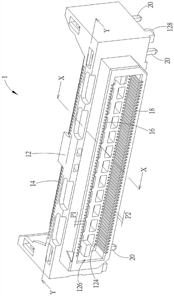
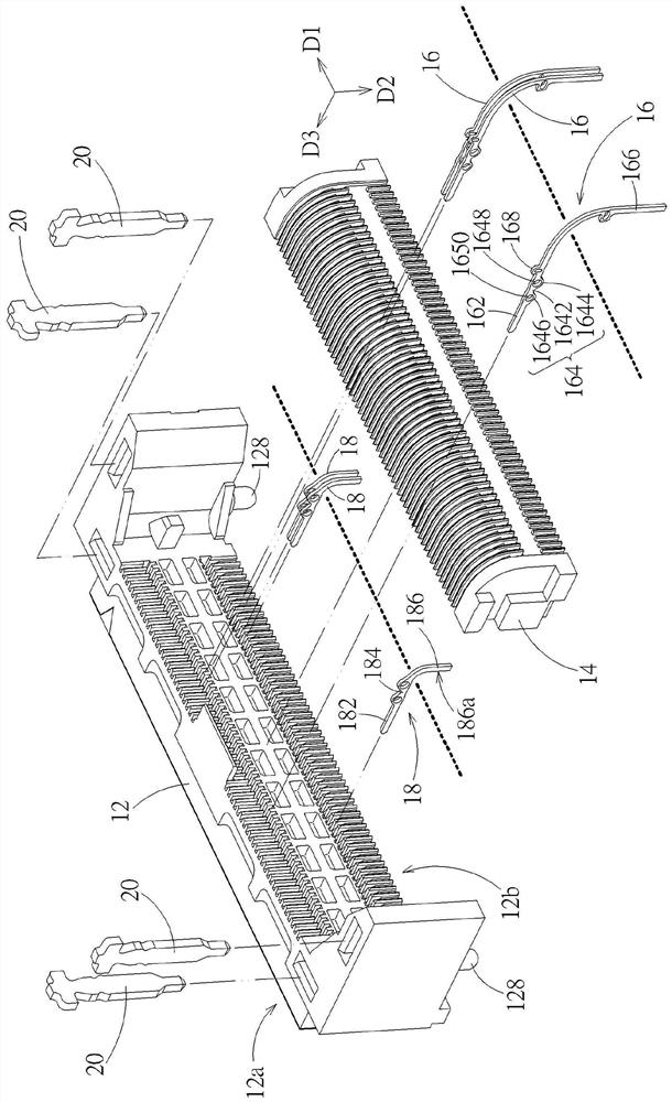
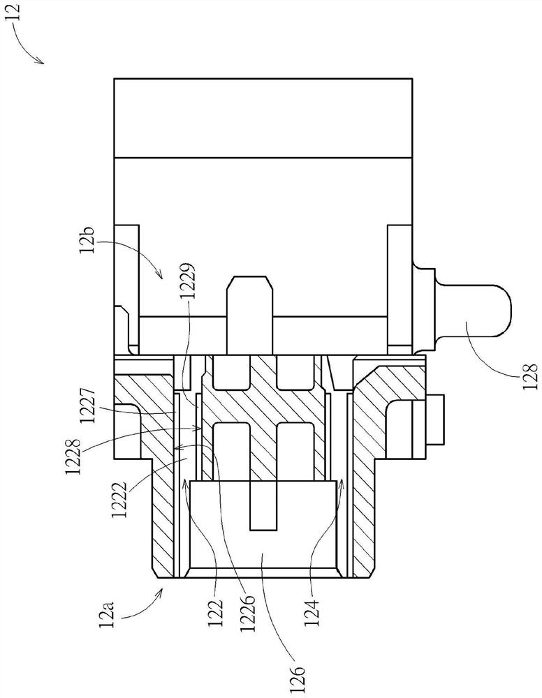
[0078] see Figure 1 to Figure 6 . An electrical connector 1 according to an embodiment of the present invention includes an insulating body 12, a rear cover 14, a plurality of upper row terminals 16 and a plurality of lower row terminals 18 (only a plurality of terminals are shown in FIG. figure 2middle). The insulating body 12 (such as but not limited to plastic injection parts) has a plurality of upper row of fixing holes 122 and a plurality of lower row of fixing holes 124 arranged in parallel and respectively corresponding to the plurality of upper row terminals 16 and the plurality of lower row terminals 18 . The upper row of terminals 16 includes a contact portion 162, a fixing portion 164, and a connecting portion 166. The contact portion 162 and the connecting portion 166 respectively extend from the fixing portion 164. The upper row of terminals 16 are fixed to the corresponding upper row of fixing holes through the fixing portion 164. In 122, the contact portion ...


PUM


Abstract

The invention provides an electric connector and a terminal thereof. The electric connector includes an insulation body and the terminal; the insulation body is provided with a fixation hole; and thefixation hole is provided with a first inner side wall and a second inner side wall opposite to the first inner side wall. The terminal includes a contact portion, a fixation portion and a connectionportion, the contact portion and the connection portion separately extend from the fixation portion and are exposed to the insulation body, the fixation portion is provided with a first side surface and a second side surface opposite to the first side surface, the fixation portion is provided with a through hole, the fixation portion is fixed in the fixation hole, the through hole is located in the fixation hole, the first side surface orients to the first inner side wall and is separated from the first inner side wall by first spacing, and the second side surface orients to the second inner side wall and is spaced apart from the second inner side wall by second spacing. The structural design makes impedance of the electric connector easy to adjust, and helps to reduce the cost and time course of development of the electric connector.

Description

technical field [0001] The invention relates to an electrical connector, in particular to an electrical connector with tuning impedance terminals. Background technique [0002] Electrical connectors are widely used in various electronic devices. Through electrical connectors, electrical connection and signal transmission can be carried out between electronic devices and between components in electronic devices. As the frequency of signal transmission increases day by day, the impact of the impedance of the electrical connector on signal transmission also increases. Under the condition of high-frequency transmission, when the electrical connector does not match the impedance of the transmission line, the electrical connector will reflect the signal, resulting in signal attenuation. The higher the degree of impedance mismatch, the more serious the signal attenuation, and finally the function of the electrical connector to transmit the signal is lost. At present, the structu...

Claims


Application Information

Patent Timeline
Patent Type & Authority Patents(China)
IPC IPC(8): H01R13/02H01R13/6474H01R13/6476H01R13/42H01R13/502H01R12/72
CPCH01R12/724H01R13/02H01R13/42H01R13/502H01R13/6474H01R13/6476
Inventor 杨策航
Owner ALL BEST PRECISION TECH
Why Eureka
Try Eureka