Eureka AIR delivers breakthrough ideas for toughest innovation challenges, trusted by R&D personnel around the world.

Light emitting module, time-of-flight camera and electronics

A module and light source technology, applied in the field of imaging, can solve problems such as eye hazards, improper laser emission, and inability to accurately detect diffuser damage, to achieve precise light sources, reduce the impact of detection accuracy, and filter out ambient light interference effect

Active Publication Date: 2022-05-13
GUANGDONG OPPO MOBILE TELECOMM CORP LTD
View PDF21 Cites 0 Cited by
  • Summary
  • Abstract
  • Description
  • Claims
  • Application Information

AI Technical Summary

Problems solved by technology

When the diffuser is damaged such as falling off or cracking, it may cause the laser to emit improperly and cause harm to the user's eyes
However, the current light emission module cannot accurately detect the damage of the diffuser

Method used


Image

  • Light emitting module, time-of-flight camera and electronics
  • Light emitting module, time-of-flight camera and electronics
  • Light emitting module, time-of-flight camera and electronics

Examples


Embodiment Construction

[0028] Embodiments of the present application are described in detail below, examples of which are shown in the drawings, wherein the same or similar reference numerals denote the same or similar elements or elements having the same or similar functions throughout. The embodiments described below by referring to the drawings are exemplary, are only for explaining the embodiments of the present application, and should not be construed as limiting the embodiments of the present application.

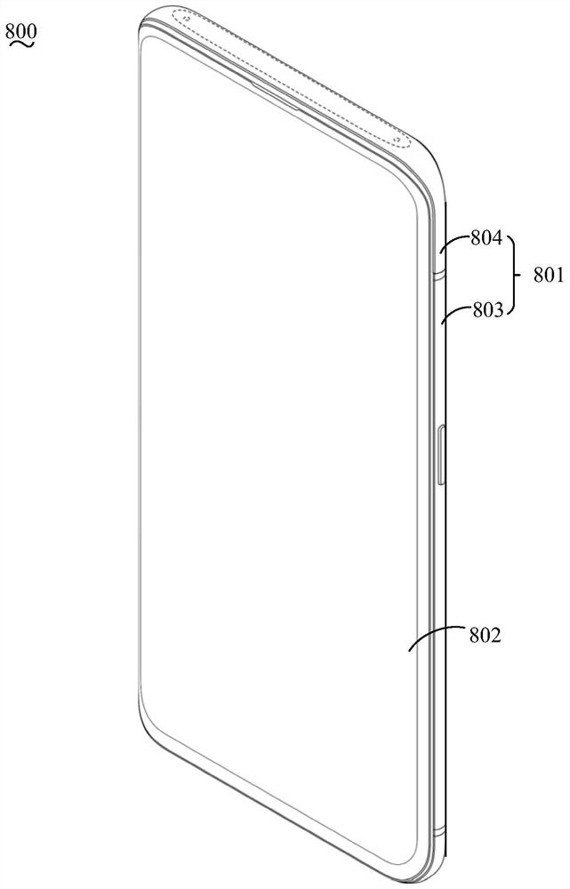
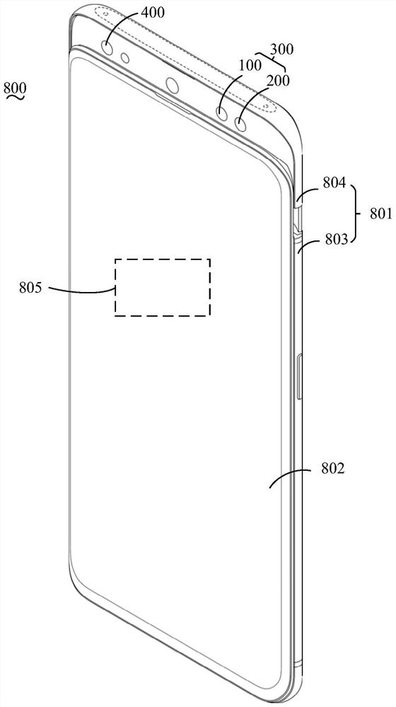
[0029] Please also refer to figure 1 and figure 2 , the electronic device 800 according to the embodiment of the present application includes a casing 801 and a time-of-flight camera 300 . The electronic device 800 may be a mobile phone, a tablet computer, a game console, a smart watch, a smart bracelet, a head-mounted display device, a drone, and the like. The embodiment of the present application is described by taking the electronic device 800 as an example of a mobile phone. It can b...


PUM

PropertyMeasurementUnit
wavelengthaaaaaaaaaa

Abstract

The application discloses a light emitting module, a time-of-flight camera and an electronic device. The light emitting module includes a light source, a diffuser, a photodetector and a processor. The light source is used to emit laser light. Diffusers are used to diffuse the laser light. The diffuser includes a light incident surface and a light exit surface opposite to each other, the light incident surface is opposite to the light source, and a high reflection film is arranged on the light exit surface. The photodetector is used to receive the laser light to form a detection electrical signal. The light detector is arranged on the side where the light incident surface is located. The processor is used for controlling the light source according to the detected electric signal. The light emitting module, the time-of-flight camera and the electronic device according to the embodiments of the present application can filter out the interference of ambient light by setting a high-reflection film on the light-emitting surface of the diffuser, and reduce the impact of ambient light on the detection accuracy of the photodetector. Therefore, the processor can accurately determine the damage of the diffuser through the detection electrical signal of the light detector, and then control the light source more precisely.

Description

technical field [0001] The present application relates to the field of imaging technology, in particular to a light emitting module, a time-of-flight camera and an electronic device. Background technique [0002] A Time Of Flight (TOF) camera is usually composed of a light emitting module and a light receiving module. The light emitting module includes a light source and a diffuser (Diffuser). When the diffuser is damaged such as falling off or cracking, the laser light may be emitted improperly, which may cause harm to the eyes of the user. However, current light emission modules cannot accurately detect damage to the diffuser. Contents of the invention [0003] Embodiments of the present application provide a light emission module, a time-of-flight camera, and an electronic device. [0004] An embodiment of the present application provides a light emitting module, the light emitting module includes a light source, a diffuser, a photodetector and a processor, the light...

Claims


Application Information

Patent Timeline
Patent Type & Authority Patents(China)
IPC IPC(8): G01S7/481G01S17/894
CPCG01S7/4811G01S17/89
Inventor 刘福
Owner GUANGDONG OPPO MOBILE TELECOMM CORP LTD
Why Eureka
Eureka Blog
Learn More