Dressing changing vehicle for surgical nursing
A technology for changing dressings and surgery, which is applied in nursing facilities, medical science, and medical equipment, etc., and can solve problems such as increased workload, multiple extractions, and low efficiency
- Summary
- Abstract
- Description
- Claims
- Application Information
AI Technical Summary
Problems solved by technology
Method used
Image
Examples
Embodiment 1
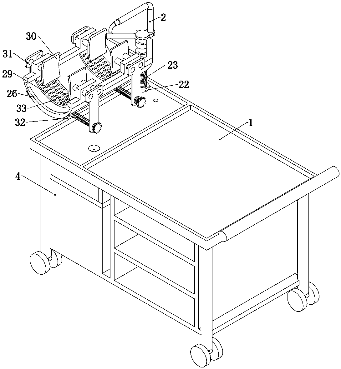
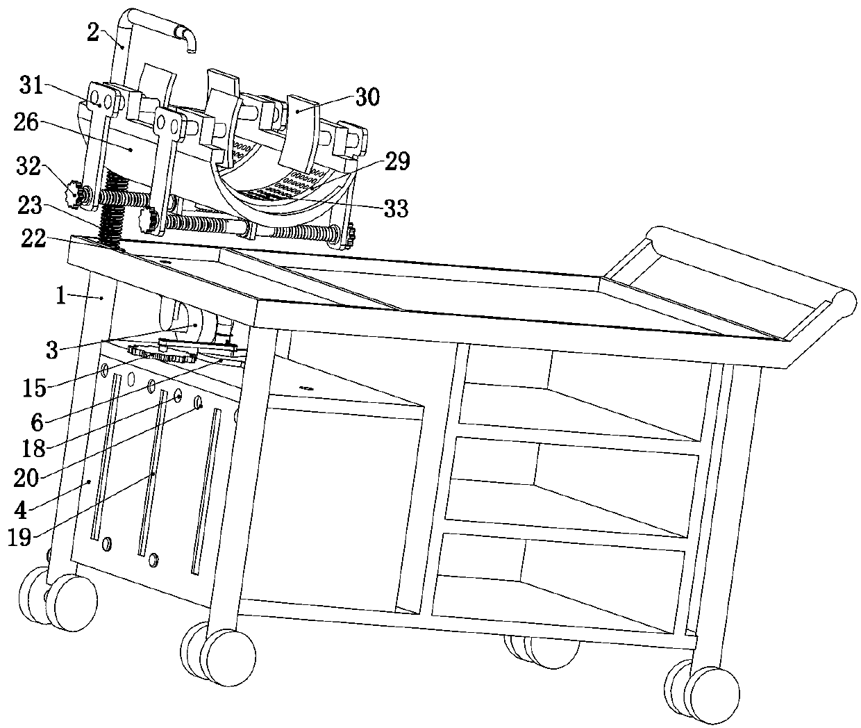
[0034] Embodiment 1. The present invention is a dressing changing cart for surgical care, which includes a trolley 1. The trolley 1 is a common trolley 1. The lower end of the trolley is rotatably connected to four universal wheels, and a plurality of storage compartments are arranged inside. It is characterized in that the trolley 1 is provided with limb clamps, and the limb clamps are used to fix the patient's limbs, so that nurses can debride, wash, and change the patient's limbs, and the limb clamps are fixedly connected with A water pipe 2, the water pipe 2 communicates with the water tank 4 fixedly connected in the trolley 1 through a hose 3;
[0035] There are two compartments 5 in the described water tank 4, and different liquids for debridement can be contained in the two compartments 5, such as distilled water, physiological saline, soapy water, etc., which can be selected according to the different needs of different departments. The number of 5 can also be increase...
Embodiment 2
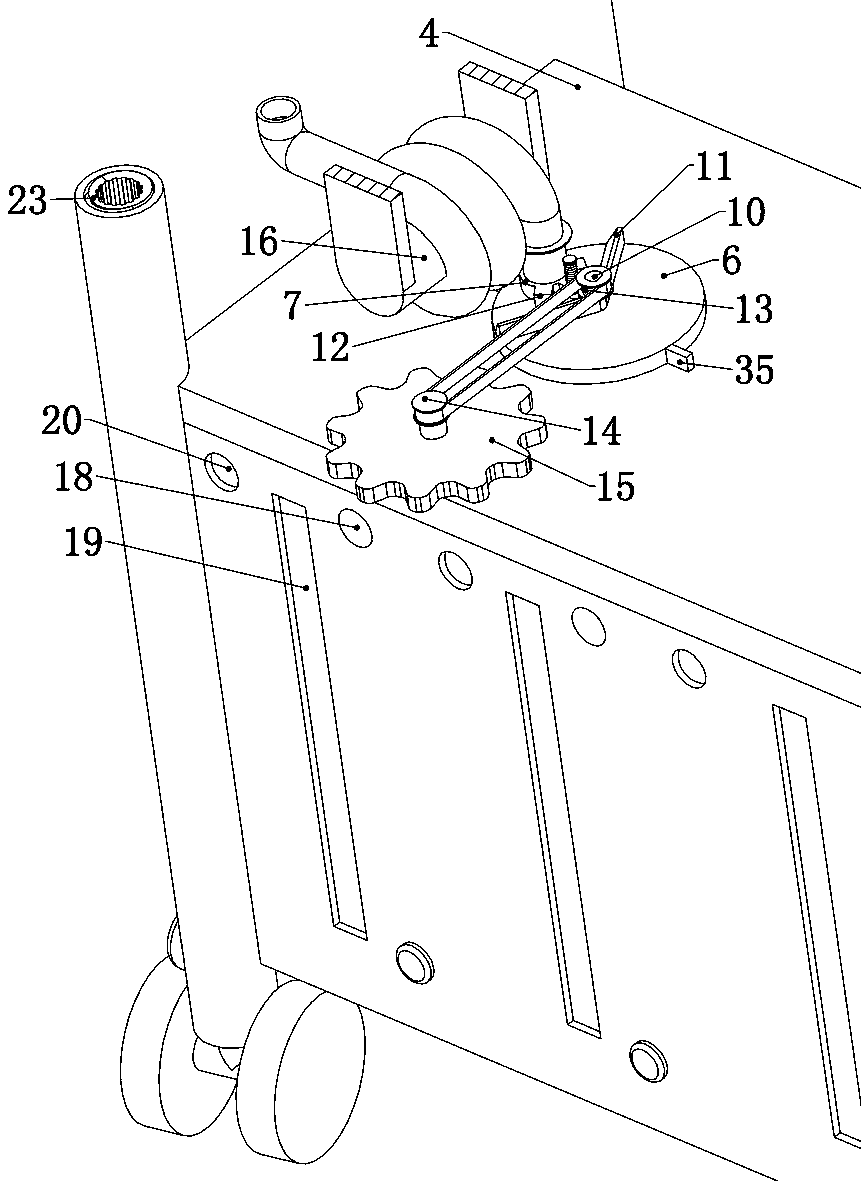
[0036] Embodiment 2, on the basis of Embodiment 1, after the transfer hole 8 and the water outlet hole 9 are aligned, the movable joint 7 will fall into the corresponding water outlet hole 9, and if it is necessary to switch the water outlet hole 9 at this time, it cannot be rotated and switched normally Disc 6, this embodiment provides a specific structure so that the movable joint 7 can be automatically lifted from the water outlet hole 9 when the switching disc 6 is turned. Specifically, refer to Figure 4 , Figure 6 , Figure 7, said switching disk 6 is rotatably connected with a push shaft 10, said push shaft 10 is fixedly connected with two push rods 11, the two push rods 11 are set at an angle less than 180° and greater than 90°, the movable joint 7 is located between the two push rods 11, the specific size of the included angle is subject to the ability to push the rotating shaft, the two push rods 11 are provided with inclined surfaces, and the two sides of the mova...
Embodiment 3
[0038] Embodiment 3, on the basis of Embodiment 1, the trolley 1 is rotatably connected with a reel 16, one end of the hose 3 communicates with the movable joint 7, and the other end bypasses the reel 16 and the The water pipe 2 mentioned above is connected, refer to figure 2 , image 3 Specifically, the lower end surface of the upper end plate of the trolley 1 is rotatably connected to a reel 16, a coil spring is provided at the rotating shaft where the reel 16 and the trolley 1 are rotatably connected, and a hose 3 is wound on the reel 16, and the hose 3 will The water pipe 2 is in communication with the movable joint 7, so as to ensure that the debridement liquid can enter the water pipe 2 smoothly from the corresponding compartment 5. When the movable joint 7 is switched to a distance from the water pipe 2, the reel 16 rotates and the hose 3 is elongated , when the movable joint 7 is switched closer to the water pipe 2, under the action of the coil spring, the hose 3 is ...
PUM
 Abstract
Description
Claims
Application Information
 - R&D
- Intellectual Property
- Life Sciences
- Materials
- Tech Scout
- Unparalleled Data Quality
- Higher Quality Content
- 60% Fewer Hallucinations
Browse by: Latest US Patents, China's latest patents, Technical Efficacy Thesaurus, Application Domain, Technology Topic, Popular Technical Reports.
© 2025 PatSnap. All rights reserved.Legal|Privacy policy|Modern Slavery Act Transparency Statement|Sitemap|About US| Contact US: help@patsnap.com


