A dual-axis vibrating mirror

A shaft vibration and bearing technology, applied in the laser field, can solve the problems of reduced life of the galvanometer, low stiffness of the torsion beam, and the influence of the vibration of the galvanometer, and achieve the effect of increasing the range of the rotation angle.

Active Publication Date: 2021-08-17
LEISHEN INTELLIGENT SYST CO LTD
View PDF7 Cites 0 Cited by
  • Summary
  • Abstract
  • Description
  • Claims
  • Application Information

AI Technical Summary

Problems solved by technology

However, this kind of torsion beam has low rigidity, and it is easy to generate stress concentration in the external vibration environment, which will reduce the life of the vibrating mirror, easily exceed the stress limit of the material, and cause damage to the vibrating mirror, or the vibrating mirror is easily affected by vibration due to low stiffness.

Method used


Image

  • A dual-axis vibrating mirror
  • A dual-axis vibrating mirror
  • A dual-axis vibrating mirror

Examples


Embodiment 1

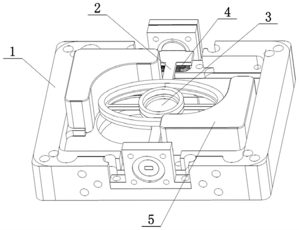
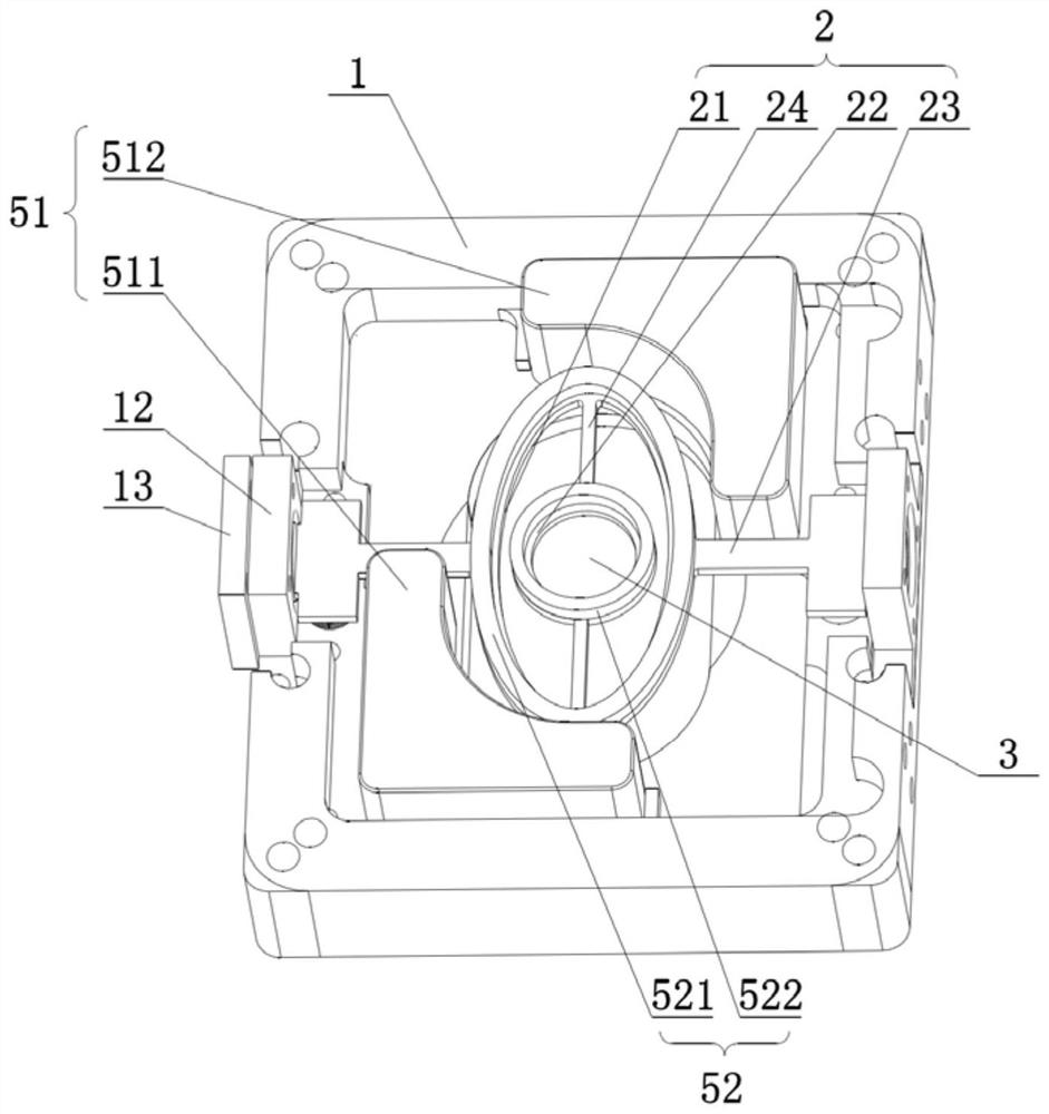
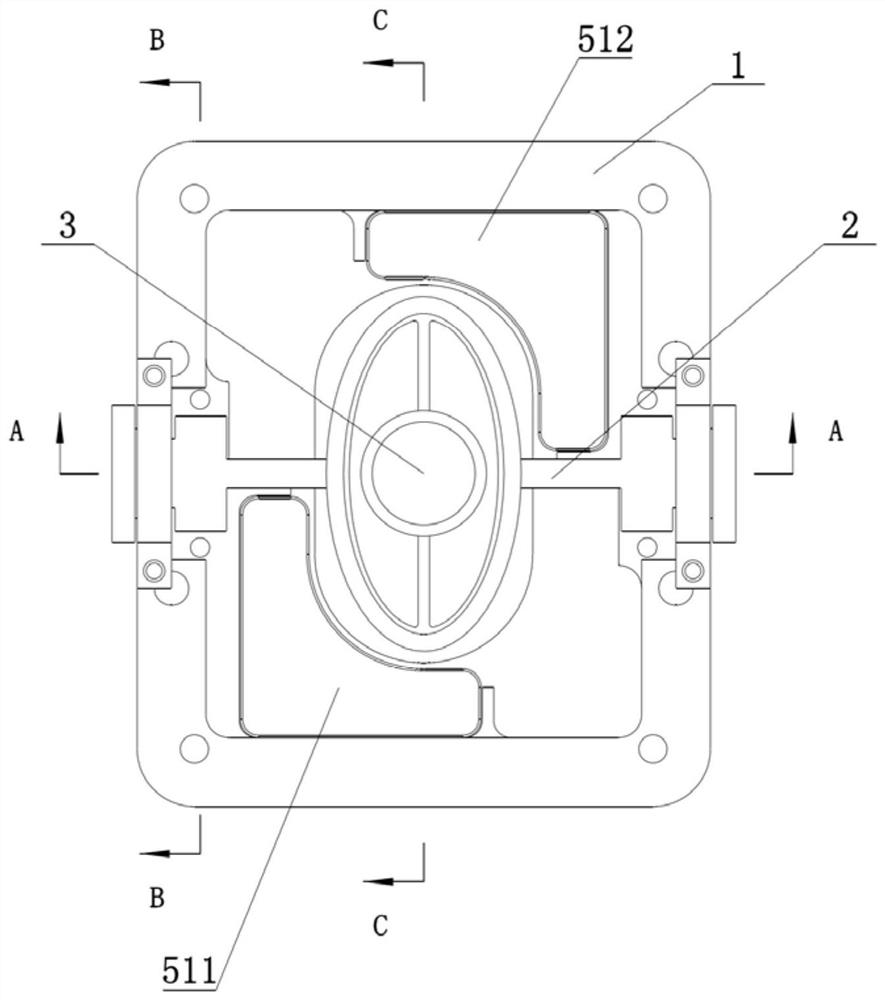
[0045] Such as Figure 1-Figure 6 As shown, this embodiment provides a two-axis vibrating mirror, including a fixing seat 1 , a support frame 2 , a mirror 3 , a reset device 4 and a driving device 5 . Wherein, the support frame 2 includes an outer frame 21, an inner frame 22, an outer support beam 23 and an inner support beam 24, the outer support beam 23 and the inner support beam 24 are perpendicular to each other, the outer frame 21 is connected to the outer support beam 23, and the outer support beam 23 Rotationally connected to the fixed seat 1, the inner frame 22 is connected to the outer frame 21 through the inner support beam 24, the reflector 3 is installed on the inner frame 22, the reset device 4 is respectively connected to the fixed seat 1 and the outer support beam 23, and the driving device 5 is set On the fixed seat 1 and the support frame 2, the support frame 2 and the reflector 3 can be driven to rotate on the axis of the outer support beam 23, and the inner ...

Embodiment 2

[0060] Such as Figure 7-Figure 10 As shown, this embodiment provides a dual-axis galvanometer. For the sake of brevity, only the differences between the present embodiment and the first embodiment are described below. In this embodiment, the reset device 4 is a reset elastic piece, both ends of the reset elastic piece are connected to the fixing base 1, and the outer support beam 23 is connected to the middle part of the reset elastic piece.

[0061] Specifically, the extension direction of the reset elastic piece is perpendicular to the outer support beam 23, and the extension lengths on both sides are symmetrical with respect to the shaft seat 12. The fixed block 15 is arranged on the fixed seat 1, and the two ends of the reset elastic piece are fixed on the fixed side by screws. Between the block 15 and the fixed seat 1.

[0062] More specifically, each section of the outer supporting beam 23 is correspondingly connected with a reset elastic piece, and each reset elastic...


PUM


Abstract

The invention belongs to the field of laser technology, and discloses a two-axis vibrating mirror, which includes a fixed seat, a support frame, a reflector, a reset device and a driving device. The support frame includes an outer frame, an outer support beam and an inner support beam, and the outer support beam and The inner support beams are perpendicular to each other, the outer frame is connected to the outer support beam, the outer support beam is rotatably connected to the fixed seat, the reflector is connected to the outer frame through the inner support beam, the reset device is respectively connected to the fixed seat and the outer support beam, and the driving device is arranged on On the fixed seat and the supporting frame, it is used to drive the supporting frame and the reflector to rotate relative to the fixed seat with the outer support beam as the axis, and drive the reset device to produce elastic deformation. The driving device is also used to drive the reflector to rotate with the inner support beam as the axis , and drive the inner support beam to produce elastic deformation. In the present invention, the arrangement of the rotational connection of the outer support beams makes it unnecessary for the outer frame to overcome the rigidity of the outer support beams when rotating, thereby increasing the range of the rotation angle of the reflector and avoiding damage caused by vibration and impact.

Description

technical field [0001] The invention relates to the field of laser technology, in particular to a dual-axis vibrating mirror. Background technique [0002] Solid-state lidar usually uses electromagnetic MEMS vibrating mirrors and MEMS-like vibrating mirrors. Electromagnetic MEMS vibrating mirrors and MEMS-like vibrating mirrors use electromagnetic force to generate torque, and the mirror rotates around the torsion beam. The drive mode of the electromagnetic galvanometer can be divided into two types, high-frequency resonant drive and low-frequency quasi-static drive. The high-frequency resonant drive uses the high-gain vibration in the resonant state of the galvanometer, which has the characteristics of high frequency and large angle. However, the resonant drive is sensitive to the environment and vibration, and position feedback must be used for closed-loop control of the vibrating mirror, and resonant scanning cannot realize the low-frequency slow-axis scanning necessary...

Claims


Application Information

Patent Timeline
Patent Type & Authority Patents(China)
IPC IPC(8): G01S7/481
CPCG01S7/4817
Inventor 胡小波郭丰收陈鼎文
Owner LEISHEN INTELLIGENT SYST CO LTD
Why Eureka
Try Eureka