Photoelectric single-spindle monitoring device and detection method

A monitoring device and photoelectric technology, applied in the field of spinning, can solve the problems of uncontrollable ring spinning, low efficiency of spinning frame, and inability to effectively improve yarn productivity and quality.

Active Publication Date: 2019-11-22
日照品特裕华纺织科技有限公司
View PDF6 Cites 8 Cited by
  • Summary
  • Abstract
  • Description
  • Claims
  • Application Information

AI Technical Summary

Problems solved by technology

[0003] The purpose of the present invention is to provide a photoelectric single-spindle monitoring device and detection method to solve the problem that the production capacity of ring spinning proposed in the above-mentioned background technology is mainly limited by the uncontrollable factors of the single-spindle state of the spinning frame, which cannot be done in the production process. Fine management of the spindle position, which makes the spinning frame in a low-efficiency running state for a long time, the yarn production capacity and quality cannot be effectively improved, and it also takes up a lot of labor.

Method used


Image

  • Photoelectric single-spindle monitoring device and detection method
  • Photoelectric single-spindle monitoring device and detection method
  • Photoelectric single-spindle monitoring device and detection method

Examples


Embodiment 1

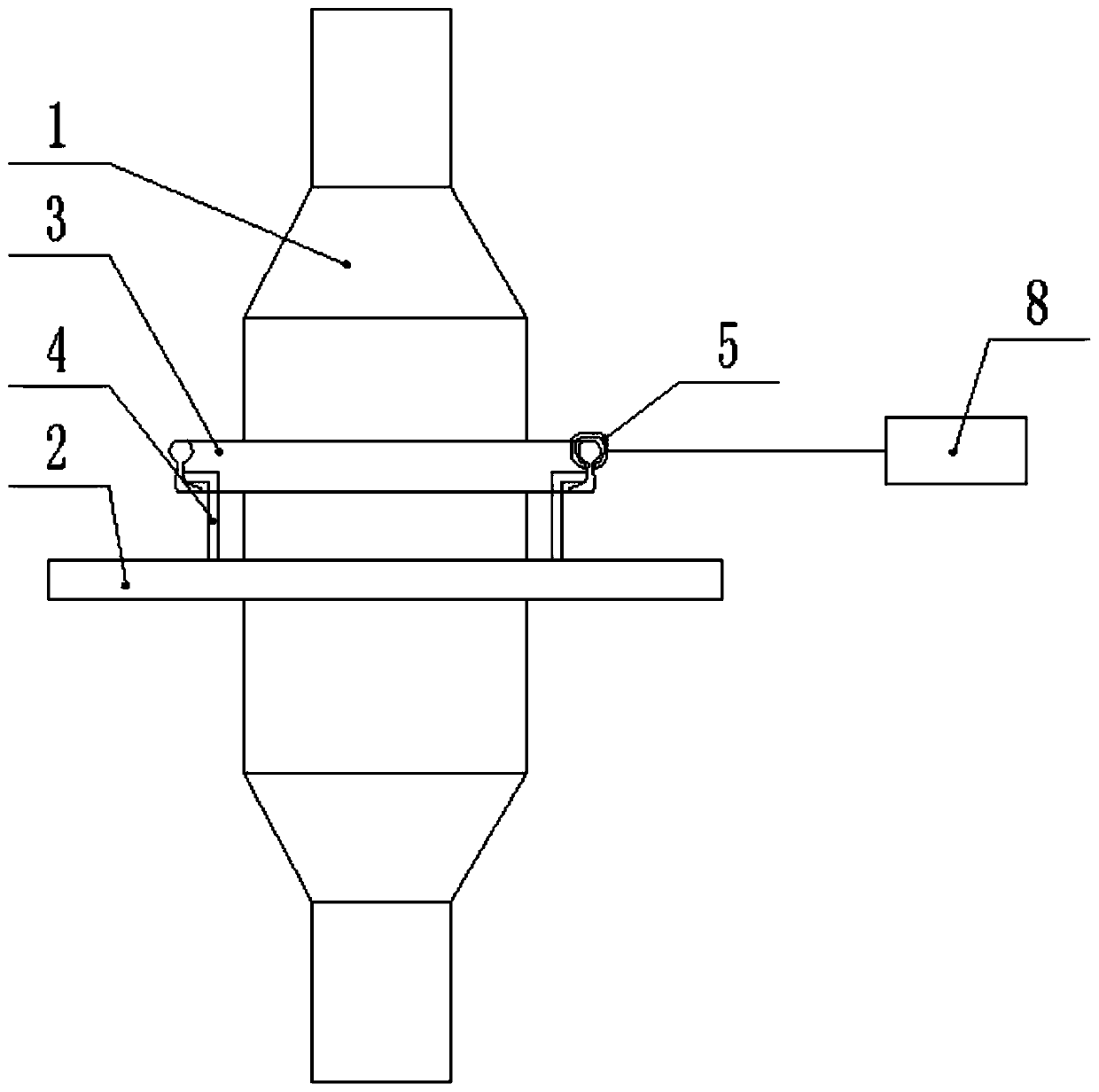
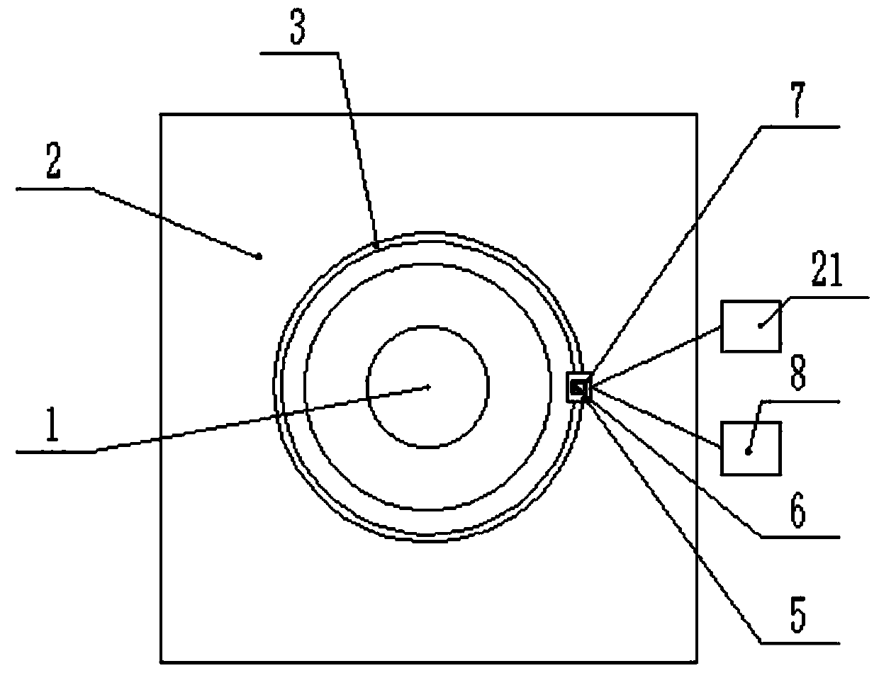
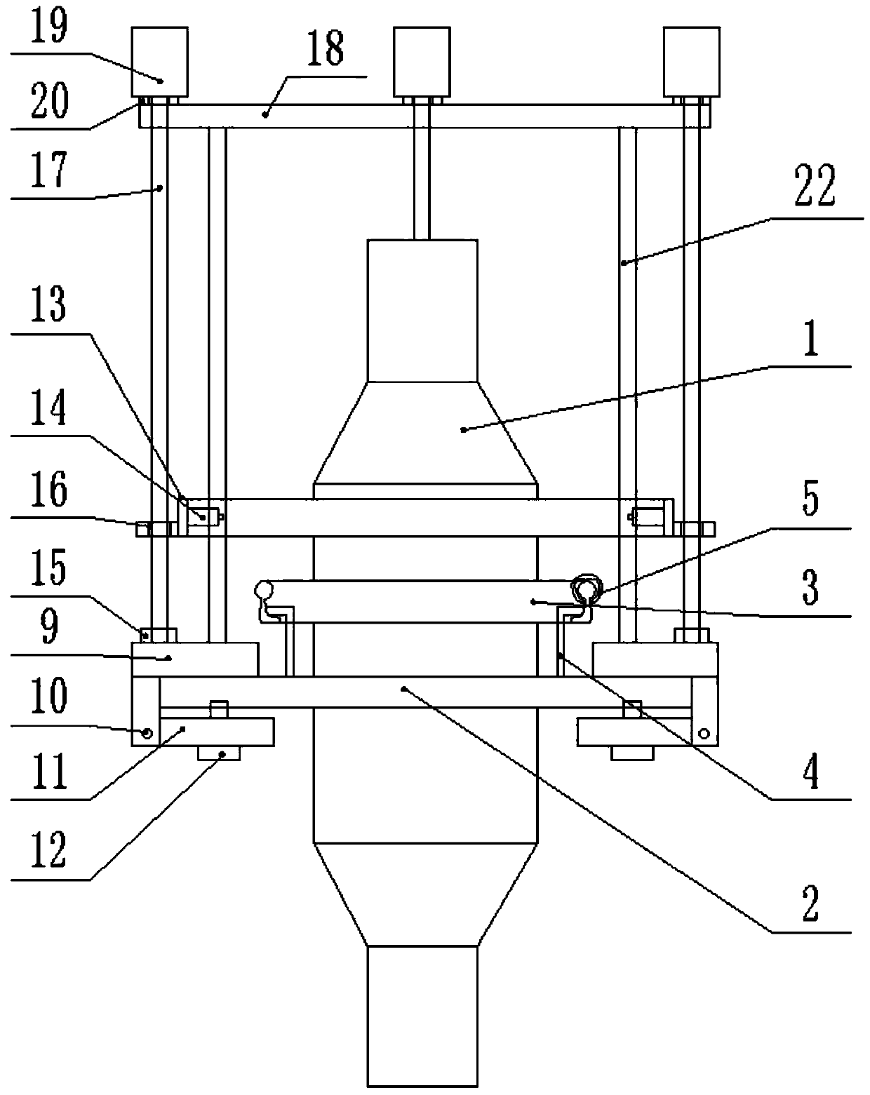
[0038] refer to Figure 1-6, a photoelectric single-spindle monitoring device, including a support plate 2, the support plate 2 includes a first plate body 201, and the center of the first plate body 201 is provided with a first installation hole 202 for passing through the bobbin 1, The periphery of the first installation hole 202 at the upper end of the first plate body 201 is fixed with a steel ring 3 through the support seat 4, a steel ring 5 is installed on the steel ring 3, and an infrared emitter 8 is installed on one side of the support plate 2 and an infrared receiver 21, a concentric detection device is detachably installed on the support plate 2, and the concentric detection device includes a fixed plate 9, and a plurality of support rods 22 are fixed on the upper end of the fixed plate 9, and the upper ends of the support rods 22 A mounting plate 18 is fixed, a stepper motor 19 is installed on the upper end of the mounting plate 18, the output shaft of the stepping...

Embodiment 2

[0040] refer to Figure 1-6 , a photoelectric single-spindle monitoring device, including a support plate 2, the support plate 2 includes a first plate body 201, and the center of the first plate body 201 is provided with a first installation hole 202 for passing through the bobbin 1, The periphery of the first installation hole 202 at the upper end of the first plate body 201 is fixed with a steel ring 3 through the support seat 4, a steel ring 5 is installed on the steel ring 3, and an infrared emitter 8 is installed on one side of the support plate 2 and an infrared receiver 21, a concentric detection device is detachably installed on the support plate 2, and the concentric detection device includes a fixed plate 9, and a plurality of support rods 22 are fixed on the upper end of the fixed plate 9, and the upper ends of the support rods 22 A mounting plate 18 is fixed, a stepper motor 19 is installed on the upper end of the mounting plate 18, the output shaft of the steppin...

Embodiment 3

[0043] refer to Figure 1-6 , a photoelectric single-spindle monitoring device, including a support plate 2, the support plate 2 includes a first plate body 201, and the center of the first plate body 201 is provided with a first installation hole 202 for passing through the bobbin 1, The periphery of the first installation hole 202 at the upper end of the first plate body 201 is fixed with a steel ring 3 through the support seat 4, a steel ring 5 is installed on the steel ring 3, and an infrared emitter 8 is installed on one side of the support plate 2 and an infrared receiver 21, a concentric detection device is detachably installed on the support plate 2, and the concentric detection device includes a fixed plate 9, and a plurality of support rods 22 are fixed on the upper end of the fixed plate 9, and the upper ends of the support rods 22 A mounting plate 18 is fixed, a stepper motor 19 is installed on the upper end of the mounting plate 18, the output shaft of the steppin...


PUM


Abstract

The invention discloses a photoelectric single-spindle monitoring device and a detection method, and relates to the technical field of spinning. A first mounting hole used for a bobbin to penetrate isformed in the center of a first plate body, and a steel collar is fixed to the periphery of the first mounting hole in the upper end of the first plate body through a supporting base; a steel ring isarranged on the steel collar, one side of a supporting plate is provided with an infrared transmitter and an infrared receiver, and a concentric detection device is detachably installed on the supporting plate; the eccentric detection device comprises a fixing plate, a plurality of supporting rods are fixed at the upper end of the fixing plate, a mounting plate is fixed at the upper ends of the supporting rods, a stepping motor is installed at the upper end of the mounting plate, an output shaft of the stepping motor is fixedly connected with a lead screw, the other end of the lead screw is connected with an inner ring of a connecting bearing fixed to the fixing plate, and a horizontal range finder is arranged on the wall of a lifting ring. By means of the infrared reflection principle, the motion state of yarn is monitored in real time by sensing the movement track of a steel wire ring and the rotation speed of the steel wire ring, so that normal information of spinning, weak twist,heavy twist, broken ends and the like is extracted.

Description

technical field [0001] The invention relates to the technical field of spinning, in particular to a photoelectric single-spindle monitoring device and a detection method. Background technique [0002] The development of ring spinning technology lags far behind open-end spinning technologies such as rotor spinning, air-jet spinning and vortex spinning mainly due to the low production capacity per spindle, while the production capacity of ring spinning is mainly limited by the single spindle state of spinning frame. Due to uncontrollable factors, fine management of the spindle position cannot be achieved in the production process, which makes the spinning frame in a low-efficiency operating state for a long time, and the yarn production capacity and quality cannot be effectively improved, and it also takes a lot of labor. Contents of the invention [0003] The purpose of the present invention is to provide a photoelectric single-spindle monitoring device and detection method...

Claims


Application Information

Patent Timeline
Patent Type & Authority Applications(China)
IPC IPC(8): D01H13/32D01H13/16
CPCD01H13/16D01H13/32
Inventor 张永龙刘文田黄秀锦崔杰
Owner 日照品特裕华纺织科技有限公司
Why Eureka
Try Eureka