Rotary type horizontally-moving trolley for intelligent parking

A rotary, mobile platform technology, applied in the field of intelligent parking, can solve the problems of unable to fix the position of the vehicle, the vehicle slips, and the single function of the mobile trolley, so as to achieve the effect of convenient operation and reasonable structure.

Inactive Publication Date: 2019-11-22
HEFEI WEIHUA INTELLIGENT PARKING EQUIP
View PDF0 Cites 0 Cited by
  • Summary
  • Abstract
  • Description
  • Claims
  • Application Information

AI Technical Summary

Problems solved by technology

[0004] The purpose of the present invention is to solve the disadvantages in the prior art that the function of the mobile trolley is single, the position of the vehicle cannot be adjusted by rotation, and the position of the vehicle cannot be fixed when the vehicle is moved, which may easily cause the vehicle to slip. A kind of rotary type transverse mobile trolley for intelligent parking

Method used


Image

  • Rotary type horizontally-moving trolley for intelligent parking
  • Rotary type horizontally-moving trolley for intelligent parking
  • Rotary type horizontally-moving trolley for intelligent parking

Examples


Embodiment 1

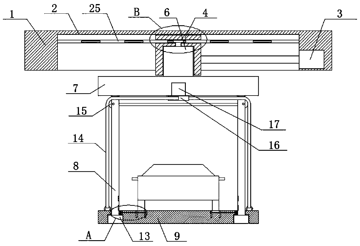
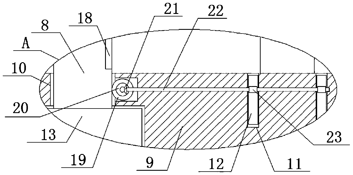
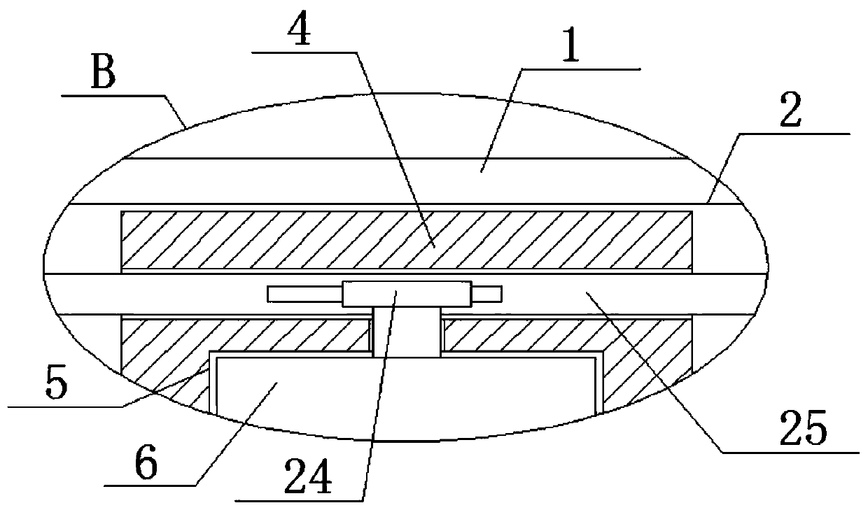
[0023] refer to Figure 1-4 , a rotary type laterally moving trolley for intelligent parking. The push rod 3 and the output shaft of the electric push rod 3 are connected to one side of the moving seat 4 through transmission. The bottom of the moving seat 4 is provided with a turning groove 5, and a turning seat 6 is installed in the turning groove 5, and the bottom of the turning seat 6 is fixedly installed. There is a mobile platform 7, the bottom of the mobile platform 7 is fixedly equipped with two side plates 8, and the side of the two side plates 8 away from each other is equipped with a winding wheel 15, and the bottom of the mobile platform 7 is provided with a base plate 9, and the bottom of the base plate 9 There are two grooves at the bottom, sliding holes 10 are opened on the top inner walls of the two grooves, the side plates 8 are slidably installed in the corresponding sliding holes 10, and bases 13 are fixedly installed on the bottoms of the two side plates 8, ...

Embodiment 2

[0029] refer to Figure 1-4 , further improvements have been made on the basis of Example 1:

[0030] A rotary type transverse moving trolley for intelligent parking, comprising a mounting table 1, a mounting groove 2 is opened at the bottom of the mounting table 1, a moving seat 4 is slidably installed in the mounting groove 2, and a The electric push rod 3, the output shaft of the electric push rod 3 is connected to one side of the moving seat 4 through transmission, the bottom of the moving seat 4 is provided with a turning groove 5, and a turning seat 6 is installed in the turning groove 5, and the bottom of the turning seat 6 passes through Bolts are fixedly installed with a mobile platform 7, and the bottom of the mobile platform 7 is fixedly equipped with two side plates 8 by bolts, and the sides of the two side plates 8 that are far away from each other are rotated and installed with a winding wheel 15, and the bottom of the mobile platform 7 is provided with a bottom ...


PUM


Abstract

The invention belongs to the field of intelligent parking, and particularly relates to a rotary type horizontally-moving trolley for intelligent parking. A following scheme is presented for solving the problems that the function of an existing moving trolley is single, a vehicle cannot be rotated and adjusted to the position, the position of the vehicle cannot be fixed when the vehicle is moved, and consequently vehicle skidding is prone to occurring. According to the scheme, the rotary type horizontally-moving trolley comprises a mounting table, a mounting groove is formed in the bottom of the mounting table, a moving seat is slidably mounted in the mounting groove, an electric pushing rod is fixedly mounted on the inner wall of the mounting groove, the output shaft of the electric pushing rod is connected to one side of the moving seat in a transmission mode, a rotary groove is formed in the bottom of the moving seat, a rotating seat is rotatably mounted in the rotary groove, and a moving table is fixedly mounted at the bottom of the rotating seat. According to the rotary type horizontally-moving trolley, the structure is reasonable, operation is convenient, the moving trolley can rotate the vehicle to adjust the position, when the vehicle is moved, the position of the vehicle can be fixed, and vehicle skidding or deviation cannot be prone to occurring.

Description

technical field [0001] The invention relates to the technical field of intelligent parking, in particular to a rotary laterally moving trolley for intelligent parking. Background technique [0002] Intelligent parking equipment can be divided into self-propelled parking equipment, semi-automatic parking equipment and fully automatic parking equipment, while fully automatic parking equipment can also be divided into two-layer or multi-layer flat automatic parking equipment, vertical intensive automatic parking equipment and Fully automatic parking equipment with a special shape and structure. In intelligent parking equipment, it is often necessary to use a mobile trolley to move the position of the parking vehicle; [0003] However, the function of the existing mobile trolley is single, the vehicle cannot be rotated to adjust the position, and the position of the vehicle cannot be fixed when the vehicle is moved, which easily causes the vehicle to slip. Contents of the inve...

Claims


Application Information

Patent Timeline
Patent Type & Authority Applications(China)
IPC IPC(8): E04H6/06E04H6/12E04H6/42
CPCE04H6/06E04H6/12E04H6/42
Inventor 曹波韦伟张普雷
Owner HEFEI WEIHUA INTELLIGENT PARKING EQUIP
Why Eureka
Try Eureka