Vehicle-mounted anti-shake deploying and controlling ball

An anti-shake and motor control technology, applied to vehicle parts, TVs, color TV parts, etc., can solve problems such as inability to solve vehicle equipment shakes, image shakes, and difficulty in capturing license plate targets, etc., to achieve mechanical anti-shake Shake function, improved image stabilization accuracy, and good anti-shake performance

Pending Publication Date: 2019-11-22
SUZHOU KEDA TECH
View PDF0 Cites 1 Cited by
  • Summary
  • Abstract
  • Description
  • Claims
  • Application Information

AI Technical Summary

Problems solved by technology

[0002] At present, most of the transmission systems of vehicle control balls in the monitoring industry are mainly belt transmission, worm helical gear transmission or worm turbine transmission; these transmission systems cannot solve the vibration problem of vehicle equipment. The jitter of the image captured by the ball makes it difficult for the lens to capture a clear license plate target

Method used


Image

  • Vehicle-mounted anti-shake deploying and controlling ball
  • Vehicle-mounted anti-shake deploying and controlling ball
  • Vehicle-mounted anti-shake deploying and controlling ball

Examples


Embodiment 1

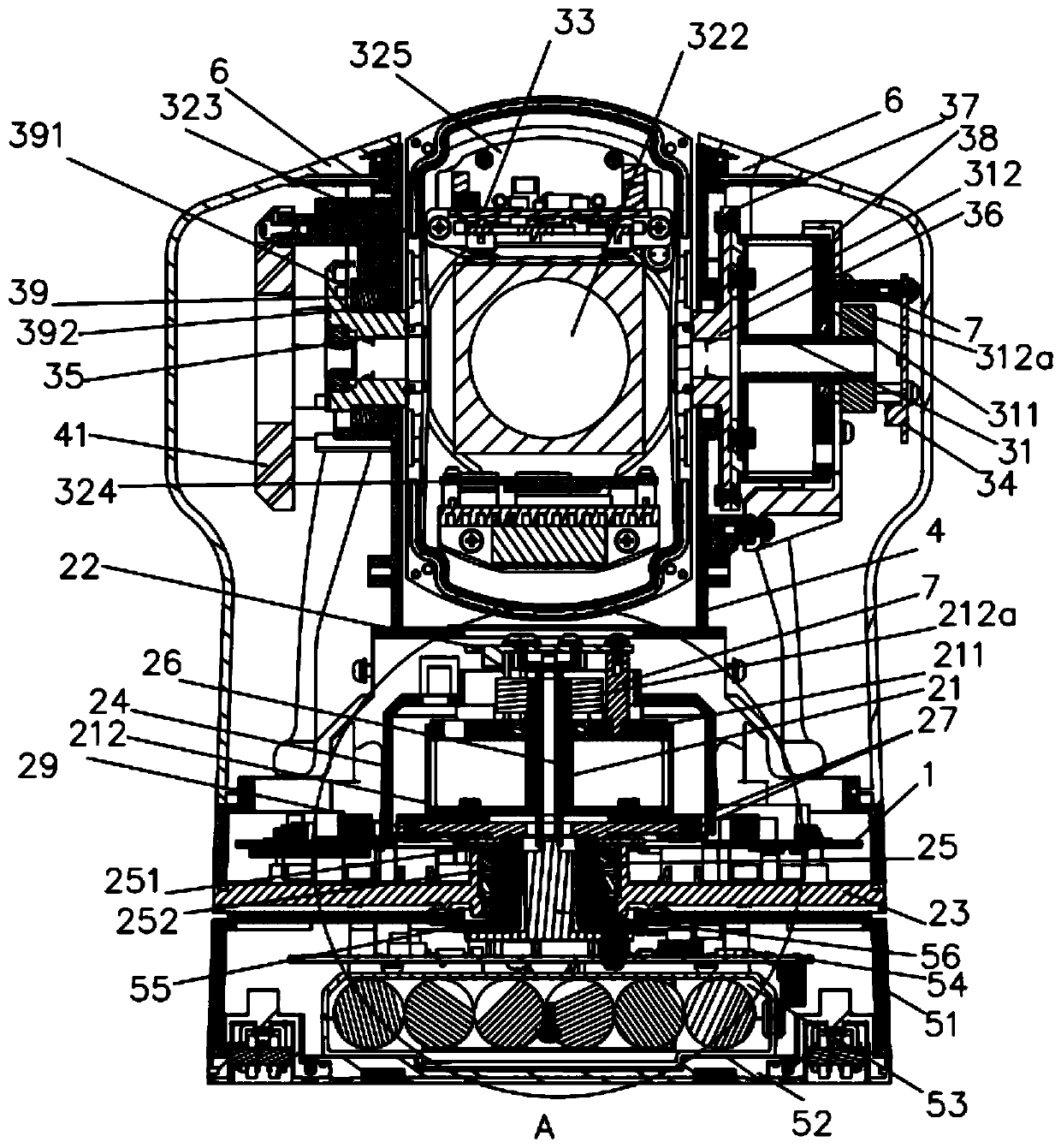
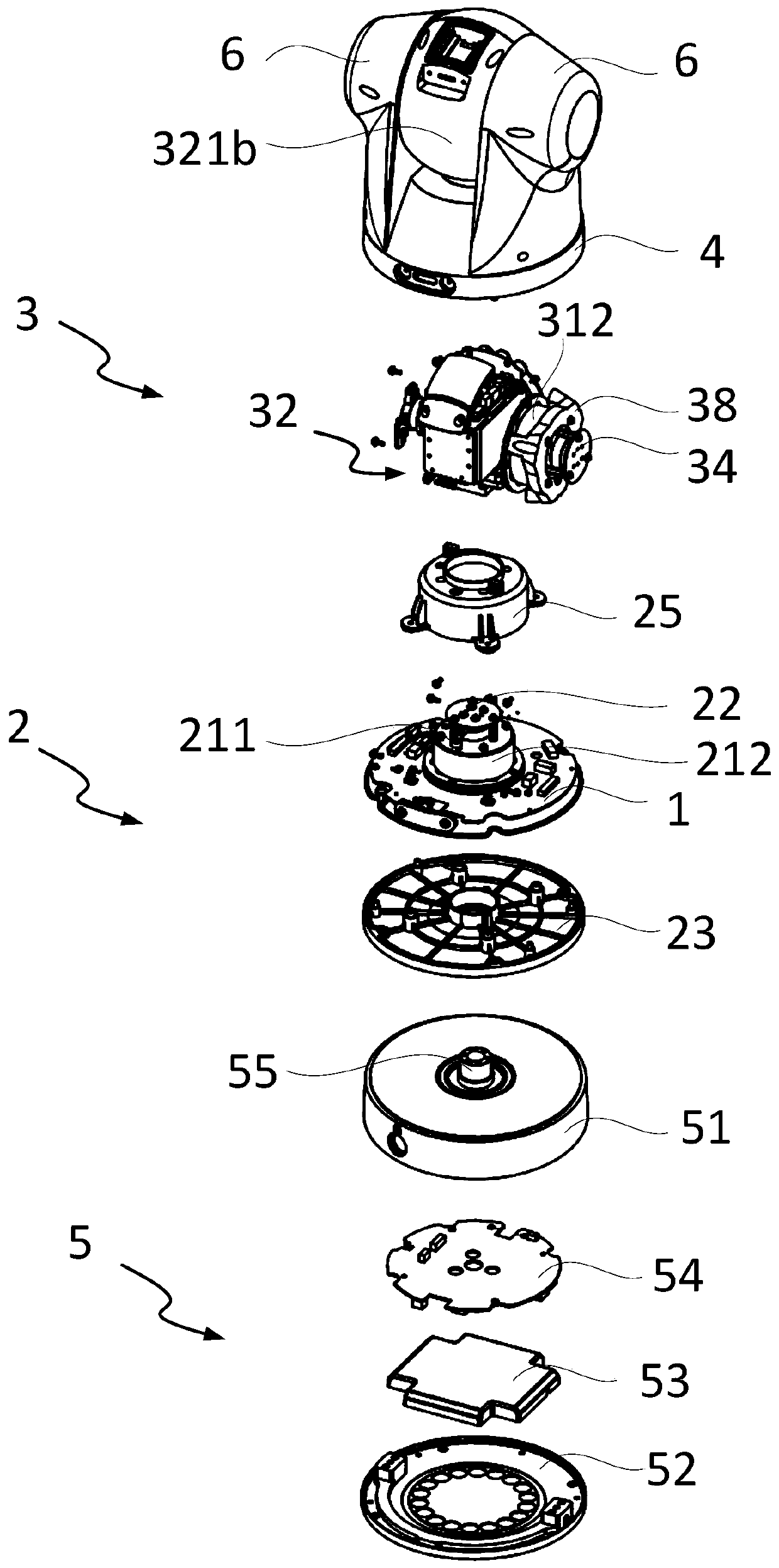
[0063] Such as figure 1 , 2 , 3, 4, and 5, the present invention provides a vehicle-mounted anti-shake cloth ball control, including an anti-shake movement assembly and a base assembly 5 for mounting on the vehicle surface, the anti-shake movement assembly and the base assembly 5 are in phase connection; among them,

[0064] The anti-shake motion assembly includes a motor control board 1, a motor, a detection unit connected to the motor for obtaining the rotational position of the motor, and a lens structure 32. The motor control board 1 is provided with a single-chip microcomputer, and inside the lens structure 32 A movement adapter plate 33 is provided, and a gyroscope for obtaining the position of the current anti-shake motion component is arranged on the movement adapter plate 33;

[0065] The motor control board 1 obtains a deviation value by comparing the position signal of the detection unit with the position signal of the gyroscope, so that the motor compensates for ...

Embodiment 2

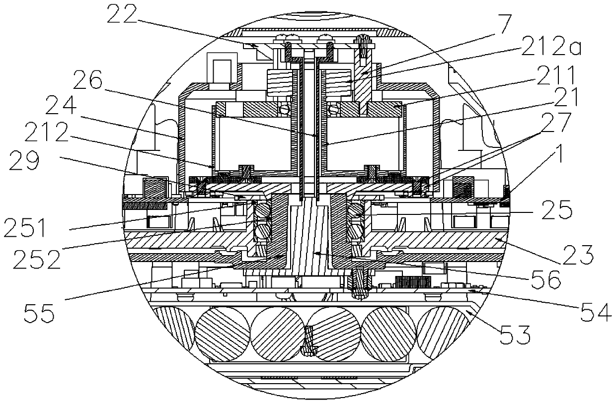
[0099] The anti-shake movement assembly does not include a horizontal rotation assembly 2, the water rotation assembly 2 is connected to the anti-shake movement assembly, and the first motor 21 is not connected with a detection unit for detecting the rotational position of the first motor 21 The first magnetic encoding control board 22, the first magnet 212a, and other technical features are the same as those in Embodiment 1.

[0100] The gyroscope is used to detect the position deviation of the vertical rotation assembly 3 and transmit the position deviation information to the TI F28069 single-chip microcomputer on the motor control board, and the single-chip microcomputer receives the vertical position detected by the MA732 magnetic encoder on the second magnetic coding control board 34 in real time. The position information of the rotating assembly 3 is compared and calculated with the position deviation information of the vertical rotating assembly 3 transmitted by the gyro...

Embodiment 3

[0102] The anti-shake movement assembly does not include a vertical rotation assembly 3, the vertical rotation assembly 3 is connected to the anti-shake movement assembly, and the second motor 31 is not connected with a detection unit for detecting the rotational position of the second motor 31 The second magnetic encoding control board 34, the second magnet 312a, and other technical features are the same as those in Embodiment 1.

[0103] The gyroscope is used to detect the position deviation of the horizontal rotation assembly 2 and transmit the position deviation information to the TI F28069 single-chip microcomputer on the motor control board, and the single-chip microcomputer receives the level detected by the MA732 magnetic encoder on the first magnetic coding control board 22 in real time. The position information of the rotating assembly 2 is compared and calculated with the position deviation information of the horizontal rotating assembly 2 transmitted by the gyroscop...


PUM


Abstract

The invention provides a vehicle-mounted anti-shake deploying and controlling ball. The ball comprises an anti-shake movement assembly and a base assembly used for being installed on the surface of avehicle. The anti-shake movement assembly is connected with the base assembly, wherein the anti-shake motion assembly comprises a motor control panel, a motor, a detection unit connected with the motor and used for obtaining the rotation position of the motor, and a lens structure, a movement adapter plate is arranged in the lens structure, and a gyroscope used for obtaining the current position of the anti-shake motion assembly is arranged on the movement adapter plate; and the motor control panel is used for comparing the position signal of the detection unit with the position signal of thegyroscope through the single-chip microcomputer to obtain a deviation value, so that the motor compensates jitter according to the deviation value, and then the lens structure is located at a set position.

Description

technical field [0001] The invention relates to the technical field of video monitoring equipment, in particular to a vehicle-mounted anti-shake cloth for ball control. Background technique [0002] At present, most of the transmission systems of vehicle control balls in the monitoring industry are mainly belt transmission, worm helical gear transmission or worm turbine transmission; these transmission systems cannot solve the vibration problem of vehicle equipment. The jitter of the image captured by the ball makes it difficult for the lens to capture a clear license plate target. [0003] Therefore, a technical problem that needs to be solved urgently by those skilled in the art is how to make the control ball have a certain anti-shake performance in the use environment. Contents of the invention [0004] In order to overcome the deficiencies in the prior art, the present invention provides a vehicle-mounted anti-shake cloth ball control, which includes an anti-shake mo...

Claims


Application Information

Patent Timeline
Patent Type & Authority Applications(China)
IPC IPC(8): H04N5/225H04N5/232B60R11/04
CPCB60R11/04H04N23/50H04N23/57H04N23/55H04N23/6812H04N23/687
Inventor 张明凯范建根匡仁军郝显波刘广泷
Owner SUZHOU KEDA TECH
Why Eureka
Try Eureka