Dual-purpose bed for sleep and massage
A dual-purpose, bed frame technology, applied in the field of dual-purpose beds, can solve the problems of unsatisfactory massage massage effect and inability to simulate the movement form of manual massage massage, achieve good massage massage effect, perfect massage function, and solve uncomfortable problems Effect
- Summary
- Abstract
- Description
- Claims
- Application Information
AI Technical Summary
Problems solved by technology
Method used
Image
Examples
example 1
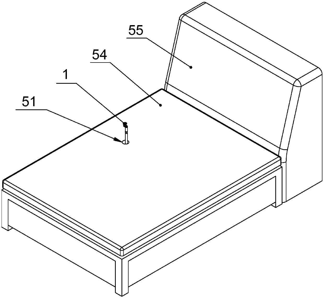
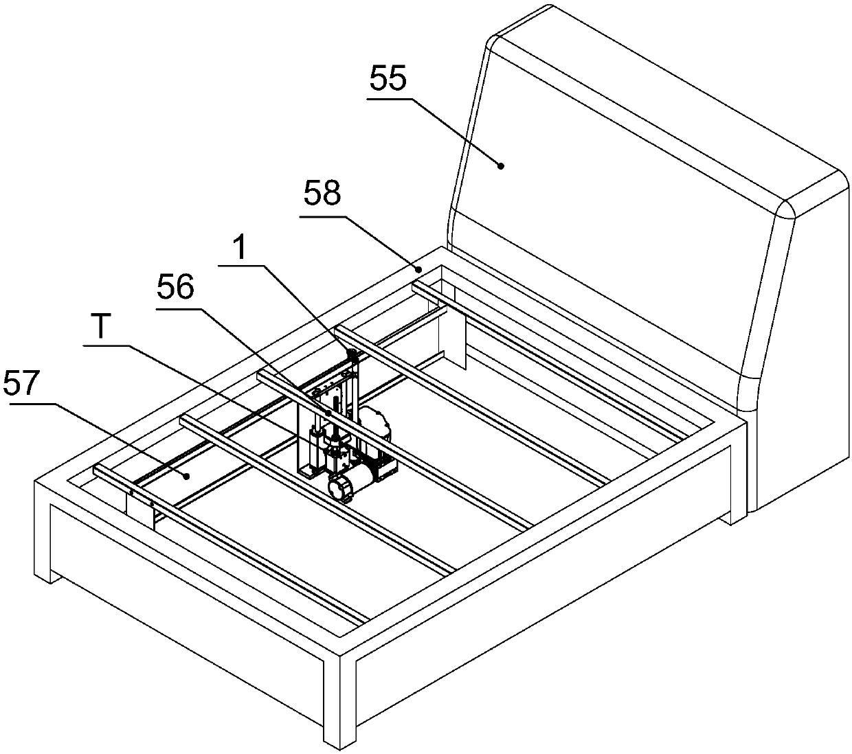
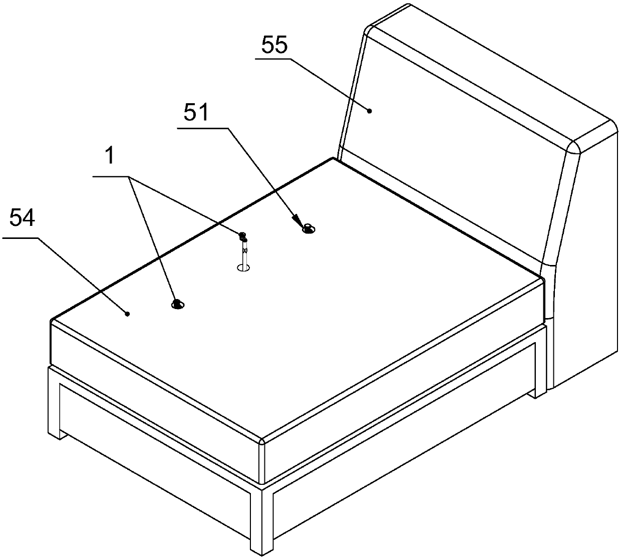
[0072] A kind of dual-purpose bed for sleeping and massage, see figure 1 , 2 , the grid-shaped bed frame 58 has a bed surface 54, and the grid-shaped bed frame 58 is provided with a mechanism mounting frame 57. The mechanism mounting frame 57 is provided with a positive and negative reciprocating pendulum massage mechanism T, and the bed surface 54 is provided with a massage head. protruding hole 51;
[0073] The positive and negative reciprocating pendulum lifting type massage mechanism T, see Figure 11 , 12 , 18, 23, 24, are provided with installation platform 5 and platform elevating frame 7; Installation platform 5 is provided with drive shaft 9 and decelerating motor 12, is connected with crankshaft 22 on the output shaft of this decelerating motor, is pivotally connected with Connecting rod 14, the other end of connecting rod 14 is pivotally connected with a rod swinging rod 15, and the transmission shaft 9 is installed and fixed at the corresponding place of the swi...
example 2
[0076] see Figure 13 , this example bed for sleeping and massage is different from the previous example in that the connecting rod 14 and the connecting rod swinging bar 15 are replaced by the sliding tube swinging rod 10 and the cylindrical sliding block 11; the cylindrical sliding block 11 is pivotally connected to the crankshaft 22, and the sliding The tube swing rod 10 is sleeved on the cylindrical slider 11, and the lower wall of the slide tube swing rod has a sliding groove for the abdication and sliding of the crankshaft-slider connecting pin, and the inner end of the slide tube swing rod 10 is fixedly connected to the transmission shaft 9. Other constructions are the same as the above example.
[0077] The crankshaft 22 drives the cylindrical slide block 11 to reciprocate, the slide block 11 drives the slide pipe swing rod 10 to swing, and the slide pipe swing rod 10 drives the transmission shaft 9 to swing back and forth.
example 3
[0079] see Figure 14 , the double-purpose bed of this example is different from Example 1 in that the connecting rod 14 and the connecting rod swinging bar 15 are replaced by the chute swinging rod 16 and the rectangular sliding block 17; the rectangular sliding block 17 is pivotally connected to the crankshaft 22, and the sliding The slot swing bar 16 is sleeved on the rectangular slider 17, and the inner end of the slot swing bar 16 is fixedly connected to the transmission shaft 9. Other constructions are the same as the above example.
[0080] The B crankshaft 22 drives the rectangular slide block 17 to reciprocate, the rectangular slide block 17 drives the chute swing bar 16 to swing, and the chute swing bar 16 drives the drive shaft 9 to reciprocate and swing.
PUM
 Abstract
Description
Claims
Application Information
 - R&D
- Intellectual Property
- Life Sciences
- Materials
- Tech Scout
- Unparalleled Data Quality
- Higher Quality Content
- 60% Fewer Hallucinations
Browse by: Latest US Patents, China's latest patents, Technical Efficacy Thesaurus, Application Domain, Technology Topic, Popular Technical Reports.
© 2025 PatSnap. All rights reserved.Legal|Privacy policy|Modern Slavery Act Transparency Statement|Sitemap|About US| Contact US: help@patsnap.com


