Vehicle seat with dampening device
A technology for vehicle seats and damping devices, which can be applied to vehicle seats, vehicle components, seat suspension devices, etc., and can solve problems such as space consumption
- Summary
- Abstract
- Description
- Claims
- Application Information
AI Technical Summary
Problems solved by technology
Method used
Image

Examples
Embodiment Construction
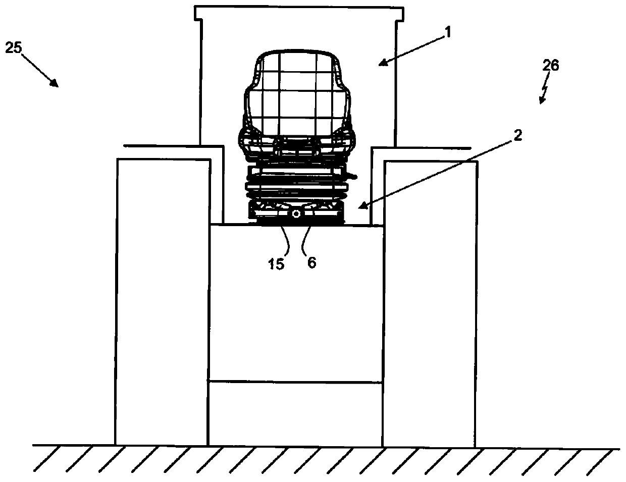
[0033] Figure 1A A vehicle seat 1 according to the invention is shown installed in the compartment of a vehicle 25 . The vehicle 25 and the corresponding vehicle seat 1 are in a normal operating state 26 and the vehicle 25 or the vehicle seat 1 is not deflected. The vehicle seat 1 has a damping device 2 which in the present case comprises a first damper 6 and a second damper 15 .
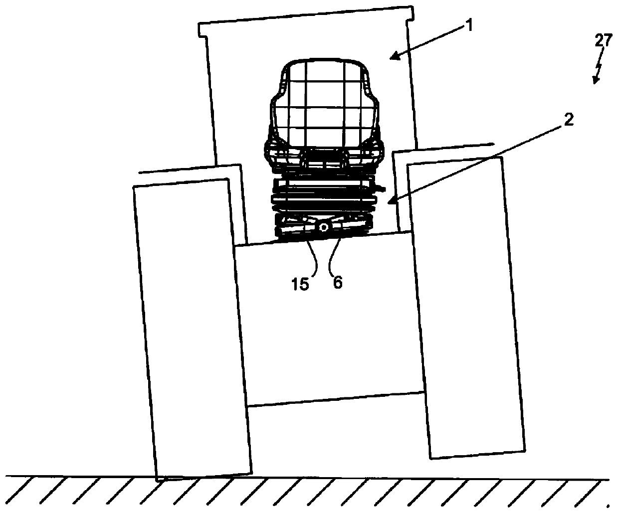
[0034] Figure 1B show Figure 1A , wherein in this case the vehicle 25 or the vehicle seat 1 is in the deflected operating state 27 . In particular, the vehicle 25 deflects only on one side, in the present case, on the right.
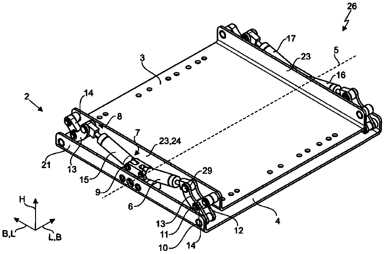
[0035] Figure 2A A particularly preferred embodiment of the damping device 2 is shown, which in the present case comprises a first damper 6 , a second damper 15 , a third damper 16 and a fourth damper 17 . Each of these dampers 6, 15, 16, 17 has a first end 7 and a second end 8, wherein the first end 7 of the damper 6, 15, 16, 17 is connected to the lower part by means...
PUM
 Abstract
Description
Claims
Application Information
PatSnap Eureka turns technology decisions into work you can execute. Powered by our Innovation Knowledge Graph, it runs expert workflows across engineering, life sciences, materials and intellectual property. Get your review-ready output in minutes.


