Disk embroidery assembly mechanism of protection type high-precision computer disk embroidery machine

A general mechanism, high-precision technology, applied in the direction of the embroidery machine mechanism, embroidery machine, automatic control embroidery machine, etc., can solve the problem of damage to the service life of the movable blade b6, affecting the normal operation of other components, and small triangle space, etc. The structure is set ingeniously, the cost of updating and maintenance is saved, and the effect of failure is not easy.

Active Publication Date: 2019-11-26
SHISHI SENKE INTELLIGENT TECH CO LTD
View PDF5 Cites 3 Cited by
  • Summary
  • Abstract
  • Description
  • Claims
  • Application Information

AI Technical Summary

Problems solved by technology

[0010] The above-mentioned thread trimming method has the following problems. The triangular space formed by the upper thread is inherently small, and the e-zone is only a part of the triangle, so the space is even smaller. The movement accuracy of the movable blade b6 and the triangular sum formed by the upper thread b1 The accuracy of the position of the bottom line b2 needs to be very high in order to improve the accuracy of cutting off the section a and the bottom line during thread trimming. However, in actual work, there are cases of miscutting, for example, when the triangle formed by the upper line b1 or the bottom line b2 is too loose or When the action angle of the movable blade b6 is too large, the hook part b61 may not be able to pass through the hollow space in the e area precisely because of the action of the hook part b61. The bottom thread b2 is not cut off, and it has to be cut again, even manually, or the hook part b61 does not pass through the triangle but passes through the side of the c section and cuts off the c section, the bottom line and the a section, so that although a section and bottom thread b2 are cut off, but the reserved section of upper thread b1 is cut off, and the reserved upper thread b1 becomes shorter and prone to thread drop. Sections a, b and c of b1 become a broken thread end, which may be stuck on the movable blade b6, affecting normal thread trimming, and after a long time, it will cause damage to the movable blade b6, that is, the service life is short. In addition, Even if it is not plugged into the moving blade b6, the broken thread end will fall into the computer embroidery machine. After a long time, it will accumulate and even cause problems affecting the normal operation of other components, resulting in mechanical failure. It may require frequent manual cleaning and maintenance. Therefore, the existing The thread-cutting method has disadvantages

Method used


Image

  • Disk embroidery assembly mechanism of protection type high-precision computer disk embroidery machine
  • Disk embroidery assembly mechanism of protection type high-precision computer disk embroidery machine
  • Disk embroidery assembly mechanism of protection type high-precision computer disk embroidery machine

Examples


Embodiment Construction

[0064] In order to further explain the technical solution of the present invention, the present invention will be described in detail below through specific examples.

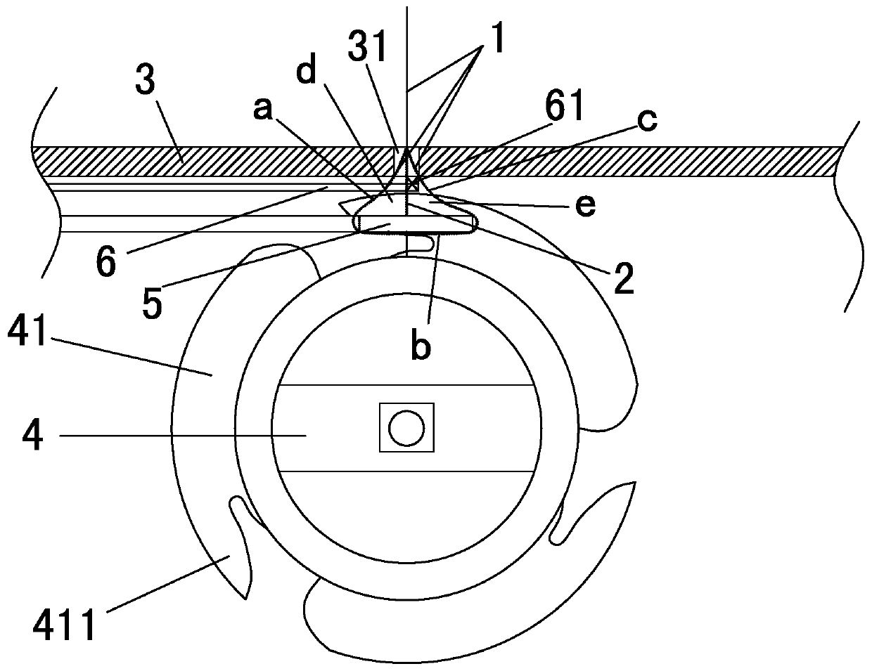
[0065] The overall coil embroidery mechanism of a protective high-precision computerized coil embroidery machine disclosed by the present invention includes an embroidery frame moving mechanism, a needle bar presser device arranged above the embroidery frame moving mechanism, and an embroidery frame arranged under the embroidery frame moving mechanism Bottom thread trimming mechanism, in this embodiment, there is a corresponding relationship between the three in the upper and lower positions. When the coil embroidery is working, they work synchronously. When not working, there may be no substantial structural connection between the three; the following is combined with the accompanying drawings Describe in detail the position connection relationship between each institution.

[0066] The needle bar presser foot d...


PUM


Abstract

The invention relates to the field of computer embroidery machines, in particular to a disk embroidery assembly mechanism of a protection type high-precision computer disk embroidery machine. The diskembroidery assembly mechanism comprises an embroidery frame moving mechanism, a needle bar presser foot device arranged above the embroidery frame moving mechanism, and a bottom thread cutting mechanism arranged on the lower portion of an embroidery frame of the embroidery frame moving mechanism. Abrasion of a rail part in the using process can be reduced by means of a movable rail of the embroidery frame moving mechanism, the structure precision is improved, and the precision, embroidery effect and working efficiency of the computer embroidery machine in embroidery work are improved. The needle bar presser foot device is provided with a lifting mechanism, the structural arrangement is ingenious and reasonable so that the damage of disk ropes can be effectively avoided, and disk embroideries are stabilized. The bottom thread cutting mechanism is an upper cutter and lower cutter thread cutting mechanism on the computer embroidery machine which is provided with a double-knife structurecapable of effectively cutting off surface threads and bottom threads, reduces the mistaken cutting rate and prolongs the service life.

Description

technical field [0001] The invention relates to the field of computer coil embroidery machinery, in particular to a coil embroidery general mechanism of a computer coil embroidery machine with protection and improved precision for coil embroidery work. Background technique [0002] Computer coil embroidery machine, also known as computer coil rope (or belt) embroidery machine, which fixes thicker rope or belt edge on the fabric by needle embroidery, such as figure 1 As shown in the structural diagram, the rope or belt 01 is fixed on the fabric 03 with the upper thread 02 advancing in a Z-shaped cross-line manner, so that the appearance of the embroidered fabric product can reflect a prominent three-dimensional embroidery effect on the surface of the fabric. It is the coil embroidery general mechanism of the computer coil embroidery machine that realizes the work of the above coil embroidery machine, that is, this mechanism is the main mechanism that realizes the coil embroid...

Claims


Application Information

Patent Timeline
Patent Type & Authority Applications(China)
IPC IPC(8): D05C7/08D05C9/00D05C11/02D05C11/20D05C13/00D05C9/20
CPCD05C7/08D05C9/00D05C9/20D05C11/02D05C11/20D05C13/00
Inventor 黄书程黄书振
Owner SHISHI SENKE INTELLIGENT TECH CO LTD
Why Eureka
Try Eureka