Needle bar presser foot device of computerized embroidery machine

A needle bar and coil embroidery technology, applied in the direction of embroidery machine, feeding device, embroidery machine mechanism, etc., can solve the problems of broken thread of light guide fiber, incomplete breakage, affecting light transmission, etc. The update of production machinery and the effect of smooth work

Pending Publication Date: 2019-11-05
泉州市睿美科绣花科技有限公司
View PDF0 Cites 0 Cited by
  • Summary
  • Abstract
  • Description
  • Claims
  • Application Information

AI Technical Summary

Problems solved by technology

[0004] The above-mentioned structure of the needle bar coiling mechanism has no problems in the ordinary coiling embroidery work, but there are relatively large problems in the work of coiling some special materials, such as the coiling rope is a light-guiding fiber, and this light-guiding fiber The fiber filament has the function of transmitting light. Its material is different from that of rope, thread or belt. The tensile strength is relatively low, and the surface cannot be damaged, otherwise it will affect the transmission of light. During coil embroidery in the rod coiling mechanism, since the needle rod coiling mechanism does not have a presser foot part that can hold down the fabric and prevent the fabric from floating up with the needle, it is easy for the floating position of the fabric to shift slightly and the next needle to pierce the fabric downward. The light guide fiber is punctured by the needle, resulting in broken thread or surface damage, incomplete breakage, etc. of the light guide fiber, which will directly cause this piece of fabric to be a waste product after embroidery. Therefore, the existing needle Rod coiling mechanism is not suitable for coil embroidery of light guide fiber, there are many problems that need to be solved urgently

Method used


Image

  • Needle bar presser foot device of computerized embroidery machine
  • Needle bar presser foot device of computerized embroidery machine
  • Needle bar presser foot device of computerized embroidery machine

Examples


Embodiment Construction

[0041] In order to further explain the technical solution of the present invention, the present invention will be described in detail below through specific examples.

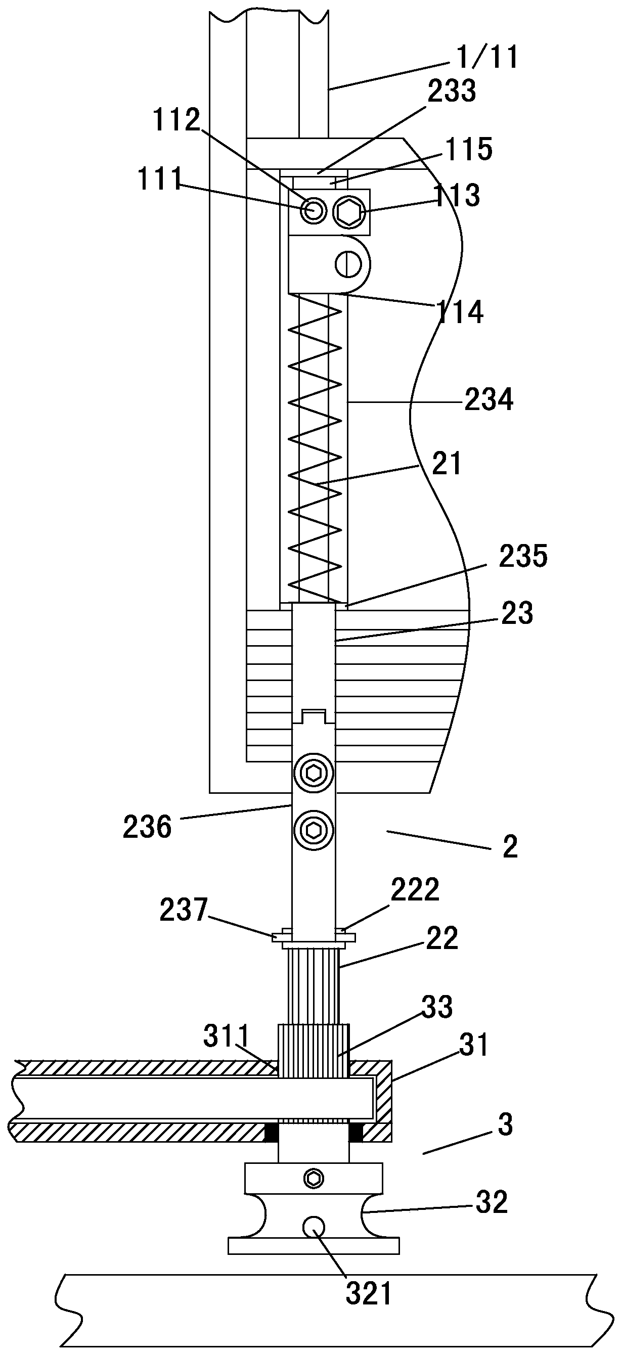
[0042] The present invention discloses a needle bar presser foot device for a computer coil embroidery machine, such as image 3 , Figure 4 , Figure 5 and Figure 6As shown, it includes a needle bar mechanism 1, a presser foot mechanism 2 and a coiling rope mechanism 3. The needle bar mechanism 1 is used for the installation and setting of the coil embroidery upper thread needle and the realization of lifting activities, and the coiled rope structure 3 is used for realizing automatic Turning to the coil rope, the presser foot mechanism 2 is used to press the fabric with the lifting movement of the needle bar. The program trace of the pattern-making software programming of design controls work, and the main difference of the present invention and prior art points out in the setting with presser foot mechani...


PUM


Abstract

The invention relates to the field of computerized embroidery machines, in particular to a needle bar presser foot device of a computerized embroidery machine. The needle bar presser foot device comprises a needle bar mechanism, a rope coiling mechanism and a presser foot mechanism, wherein the needle bar mechanism comprises a needle bar, the needle bar is of a hollow structure, and a threading hole leading to the hollow structure is formed in the side wall of the needle bar; the rope coiling mechanism comprises a mounting plate, a rope coiling sleeve ring and a transmission sleeve, the presser foot mechanism comprises a spring, a presser foot member and a lifting and pressing member, the presser foot member penetrates into the transmission sleeve and the rope coiling sleeve ring, and thepresser foot member penetrates into the transmission sleeve in a structure that the presser foot member can move axially up and down but is not rotatable about the axis; the lifting and pressing member comprises a lifting pull bar and a lifting press bar, one end of the lifting press bar is a lower connecting end, the other end of the lifting press bar is a lower pressing top holding end, the lower end of the spring is held on the lower pressing top holding end, the lower end of the lifting pull bar is connected with the lifting press bar, the needle bar is provided with a lifting pull part, the upper end of the lifting pull bar is a lifting pull end, and the lifting pull part pushes the lifting pull end when the needle bar rises. The device is ingenious and reasonable in structure and canachieve the effects of effectively avoiding damage to a coiled rope and stabilizing the embroidery.

Description

technical field [0001] The invention relates to the field of computerized embroidery machinery, in particular to a needle bar presser foot device of a computerized disk embroidery machine. Background technique [0002] Computer coil embroidery machine, also known as computer coil rope (or belt) embroidery machine, which fixes thicker rope or belt edge on the fabric by needle embroidery, such as figure 1 As shown in the structural diagram, the rope or belt 01 is fixed on the fabric 03 with the upper thread 02 advancing in a Z-shaped cross-line manner, so that the appearance of the embroidered fabric product can reflect a prominent three-dimensional embroidery effect on the surface of the fabric. [0003] This kind of computer rope embroidery machine achieves the work of side disk and side needle embroidery mainly through the needle bar coil rope mechanism on the main machine head, such as figure 2 As shown in , the lifting of the needle bar 04 is realized by the control sys...

Claims


Application Information

Patent Timeline
Patent Type & Authority Applications(China)
IPC IPC(8): D05C9/20D05C11/06D05C11/02D05C11/04D05C7/08
CPCD05C7/08D05C9/20D05C11/02D05C11/04D05C11/06
Inventor 黄书程黄书振
Owner 泉州市睿美科绣花科技有限公司
Why Eureka
Try Eureka