Washing apparatus

a technology of washing machine and wash water, which is applied in the direction of other washing machines, cleaning using liquids, textiles and paper, etc., can solve the problems of inability to accurately sense the leakage of wash water, troublesome water leakage sensors, and malfunction of constituent elements, so as to reduce processing costs and material costs, the effect of simplifying the structur

Inactive Publication Date: 2006-04-20
LG ELECTRONICS INC
View PDF10 Cites 27 Cited by
  • Summary
  • Abstract
  • Description
  • Claims
  • Application Information

AI Technical Summary

Benefits of technology

[0034] Fourthly, the holders take the form of hooks, which protrude upward from the top of the base pan and serve to guide the water leakage sensor into a predetermined assembling position and to allow the water leakage sensor to be caught after being press-fitted to the base pan. The hooks can secure the position of the water leakage sensor, and can achieve a reduction in processing costs and material costs by virtue of their simplified structure.
[0035] Fifthly, the washing apparatus according to the present invention comprises spacers, which protrude from one of the bottom of the water leakage sensor, the top of the base pan, and the hooks, so that the bottom of the water leakage sensor is spaced apart from the top of the base pan. Spacing the water leakage sensor from the base pan has the effect of preventing a float of the water leakage sensor from being unintentionally raised by water remaining on the base pan, etc. Thereby, the water leakage sensor can accurately operate only when the amount of water introduced into the water leakage sensor exceeds a predetermined value, thereby eliminating the risk of sensor malfunction.
[0036] Sixthly, the washing apparatus according to the present invention comprises couplers for allowing the water leakage sensor to be coupled to the base pan while sliding on the top of the base pan. This ensures easy mounting of the water leakage sensor.
[0037] Seventhly, the couplers according to the present invention include: guide protrusions provided at the water leakage sensor; and guide ribs provided at the top of the base pan and having guide grooves for the insertion of the respective guide protrusions. With the use of the guide protrusions and the guide ribs, the water leakage sensor can be assembled to the base pan via sliding movement thereof. This achieves an enhancement in simplicity and efficiency of the assembling operation and can reduce manufacturing costs of the water leakage sensor by virtue of simplified structure thereof.
[0038] Eighthly, the guide protrusions and the guide grooves are configured so that their cross sectional areas are gradually reduced in a direction that the guide protrusions slide along the guide grooves, so that the water leakage sensor can be assembled only in a single direction. This enables firm fixation of the water leakage sensor.
[0039] Finally, the water leakage sensor according to the present invention may have a cubic shape. This facilitates connection of a wire to a sensing element of the water leakage sensor, resulting in an enhancement in assembling efficiency.

Problems solved by technology

However, the prior art washing apparatus as stated above has a problem in that it often suffers from malfunction of constituent elements thereof when the wash water leaks from the tub, water supply device or water drainage device during operation.
In view of the forgoing problem, although it has been recently proposed to mount a water leakage sensor to the top of the base pan, most conventional water leakage sensors are very troublesome to mount to the base pan, and are unable to accurately sense the leakage of wash water unless the wash water falls in the vicinity of the water leakage sensors.

Method used


Image

  • Washing apparatus
  • Washing apparatus
  • Washing apparatus

Examples


first embodiment

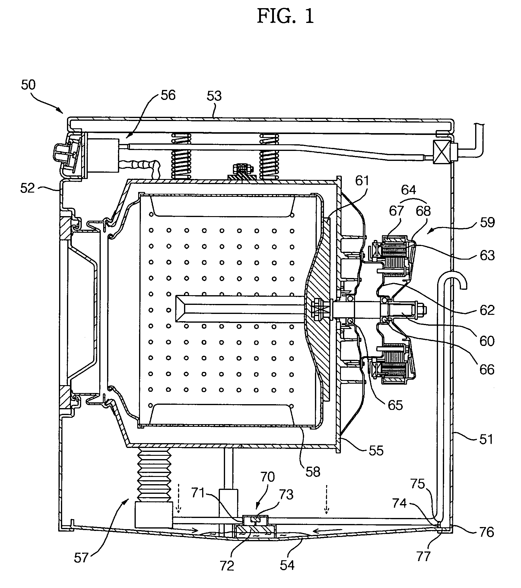
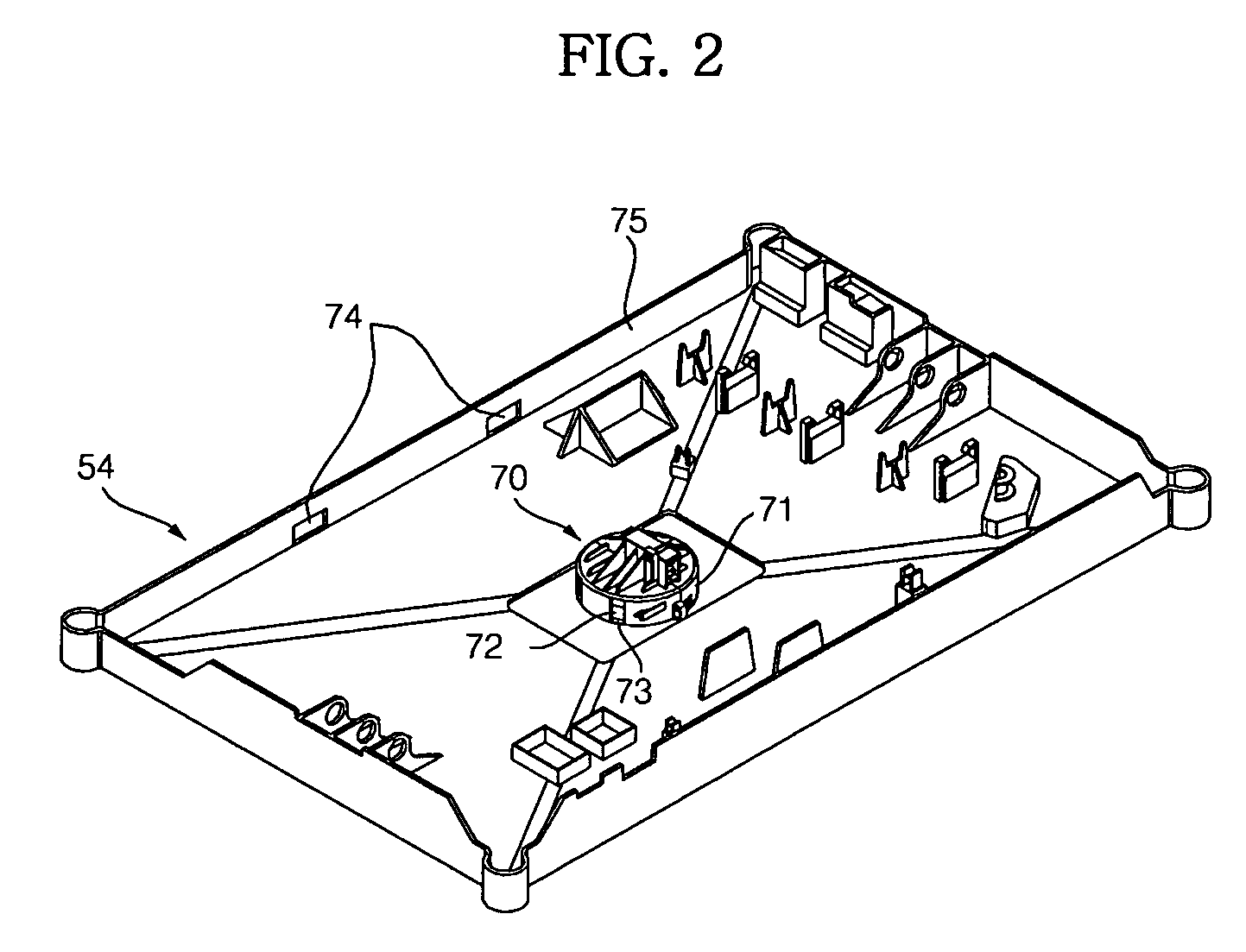
[0054] As shown in FIGS. 1 and 2, the washing apparatus according to the present invention is a washing machine for washing laundry using detergent and water. The washing machine comprises: a casing 50 forming the outer appearance of the washing machine and having a laundry entrance / exit opening formed at a front side thereof; a tub 55 supported in the casing 50 in a shock-absorbing manner; a water supply device 56 to supply detergent or wash water into the tub 55; a water drainage device 57 to drain the wash water in the tub 55 to the outside of the casing 50; a drum 58 rotatably disposed in the tub 55 to receive laundry therein; and a motor 59 to rotate the drum 58.

[0055] The casing 50 includes: a cabinet body 51 having open front and upper sides; a cabinet cover 52 mounted to the open front side of the cabinet body 51; a top cover 53 mounted to the open upper side of the cabinet body 51; and a base pan 54 mounted to a lower end of the casing 50 to form the bottom of the casing 50...

second embodiment

[0079]FIG. 3 is a side sectional view illustrating a washing apparatus according to the present invention.

[0080] The washing apparatus according to the second embodiment of the present invention is a drying machine for blowing dry hot air into a certain space that accommodates wet laundry to dry the laundry. As shown in FIG. 4, the drying machine comprises: a casing 80 forming the outer appearance of the drying machine; a drum 81 rotatably disposed in the casing 80 and having open front and rear sides to put or take the laundry into or out of the drum 81, a plurality of lifters being provided at an inner peripheral surface of the drum 81 to raise and drop the laundry; and a heater assembly 82 mounted to the casing 80 to heat outside air introduced into the casing 80.

[0081] The drying machine further comprises: a supply duct (not shown) to supply dry hot air, having passed through the heater assembly 82, into the drum 81; an exhaust duct 83 to discharge the used air, which became hi...

third embodiment

[0093]FIG. 4 is a side sectional view illustrating a washing apparatus according to the present invention.

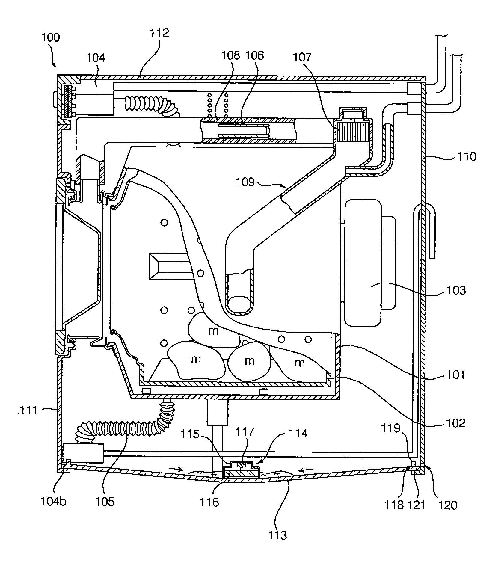
[0094] The washing apparatus according to the third embodiment of the present invention is a combined washing and drying machine for washing laundry using appropriate detergent and water while applying mechanical force and, successively, drying the washed laundry. As shown in FIG. 4, the combined washing and drying machine comprises: a casing 100 forming the outer appearance of the machine; a tub 101 horizontally mounted in the casing 100; a drum 102 mounted in the tub 101 to receive laundry therein; a motor 103 to rotate the drum 102; a water supply device 104 to supply detergent or wash water into the tub 101; a water drainage device 105 to drain the wash water received in the tub 101 to the outside of the casing 100; a drying duct located above the tub 101 and configured to accommodate a heater 106 and a blowing fan 107, which serve to discharge hot air into the tub 101; and ...


PUM


Abstract

Disclosed herein is a washing apparatus in which the top of a base pan is inclined downward toward a mounting position of a water leakage sensor, so that water, dropped onto the base pan, is gathered toward the water leakage sensor regardless of a water drop position, thereby enabling prompt operation of the water leakage sensor and achieving an enhancement in reliability. Furthermore, the washing apparatus comprises holders by which the water leakage sensor is vertically caught after being vertically press fitted to the base pan, thereby enabling the water leakage sensor to be mounted to the base pan via a single vertical press-fitting operation, resulting in an enhancement in assembling efficiency.

Description

BACKGROUND OF THE INVENTION [0001] 1. Field of the Invention [0002] The present invention relates to a washing apparatus, and, more particularly, to a water leakage sensing structure of a washing apparatus, in which the top of a base pan is inclined downward toward a water leakage sensor to induce prompt operation of the water leakage sensor and the water leakage sensor can achieve a reduction in assembling costs by virtue of simplified structure and assembling operation thereof. [0003] 2. Description of the Related Art [0004] Generally, washing apparatuses are classified into washing machines for washing laundry using detergent and water, drying machines for drying wet laundry using dry hot air, and combined washing and drying machines having both washing and drying functions. [0005] Considering the configuration of a prior art washing apparatus, it comprises: a casing forming the outer appearance of the washing apparatus; a tub mounted in the casing to receive wash water therein; ...

Claims


Application Information

Patent Timeline
Patent Type & Authority Applications(United States)
IPC IPC(8): D06F37/00D06F39/00
CPCD06F39/081D06F39/12
Inventor CHOI, DONG HAKIM, SOO BONGLEE, KYU HWANAHN, YONG JINKIM, MIN HO
Owner LG ELECTRONICS INC
Why Eureka
Try Eureka