Electromagnetic detector for marine surveying

a technology of electromagnetic detectors and electromagnetic detectors, applied in the field of seafloor electromagnetic detectors, can solve the problems of time-consuming deployment, difficult to accurately determine the orientation of the dipole antennae comprising the detector on the seafloor, and the conventional detectors for em surveying suffer from a number of problems, so as to improve the accuracy of measurement statistics

Inactive Publication Date: 2008-12-18
OHM
View PDF1 Cites 26 Cited by
  • Summary
  • Abstract
  • Description
  • Claims
  • Application Information

AI Technical Summary

Benefits of technology

[0037]The detector may further comprise a compass and / or an inclinometer to record its orientation on the seafloor. This can assist in resolving measured field components into desired directions for analysis, e.g. for resolving the measured fields into horizontal and vertical components.
[0038]The detector may comprise a fifth electrode mounted between the first and fourth electrodes. This allows two spatially separated measurements of electric field to be measured along the first direction. Not only can this improve measurement statistics, but the two spatially separated measurements of electric field can allow for a determination of the local gradient in the field. This can be useful for some analysis schemes, for example those described in GB 2 411 006 A [9] and GB 2 423 370 A [10].

Problems solved by technology

Although good signal to noise ratios can be achieved with these instruments, they are time consuming to deploy since they must be deep-towed through the water column and released close to the seafloor.
Conventional detectors for EM surveying suffer from a number of problems.
The present inventors have appreciated that this makes it difficult to accurately determine the orientation of the dipole antennae comprising the detector on the seafloor.
This can be problematic because valuable information regarding the subterranean strata can be obtained using full vector information on measured EM fields (i.e., by taking account of the directions of EM fields, as well as their amplitudes and phases).
Furthermore, inaccurate orientation information causes problems in accurately determining spatial gradients in EM fields which are important in some analysis schemes because they are particularly sensitive to lateral structural variations in subterranean strata, and may also be used to de-convolve measured fields into “pure” TE and “pure” TM components which are more amenable to some types of further analysis, e.g., as described in GB 2 411 006 A [9] and GB 2 423 370 [10] (the raw EM field data are in general mixed mode for arbitrary source orientations and detector locations).
Accurate orientation information is difficult to obtain for detectors of the type shown in FIG. 2 because while the orientation of the main body of the unit may be determined using an appropriate on-board compass device, the booms themselves will typically have flexed during their descent through the water column.
This means the orientation of the receiver dipoles provided by the electrodes is typically not known to an accuracy of any better than 5 degrees or so, whereas 1 degree accuracy or better is desired for accurate use of orientation information.
Furthermore, the semi-rigid nature of the booms of detectors such as shown in FIG. 2 renders them prone to motionally induced noise.
Firstly, it causes changes in the direction along which electric fields are measured, and secondly the movement of the antennae and their associated cabling through the Earth's magnetic field induces electric fields in the measurement channels.
These effects can mean motionally induced noise becomes the dominant source of noise, especially in shallow water and areas with extreme seafloor currents.
A further problem with known marine EM surveying detectors arises from the fact that the signals to be measured are extremely small.
This can be particularly problematic for stand alone seafloor deployed type detectors such as shown in FIGS. 2 and 3 since the relatively small scale of these detectors (compared to long-wire detectors) means the voltage difference between their electrodes will typically be only 10 nV or so (for electrodes separated by 10 m).
The difficulty in measuring such small voltages is exacerbated by the remote location and the hostile environment in which detectors are located.
Thus the signals to be measured can easily become contaminated by noise arising from connectors and cabling to the extent that the signals can become completely lost in noise if the connectors become worn or corroded by seawater.
For example, the vertical component will almost always be particularly weak because there is generally little vertical signal.
When combining signals from the three spatial directions to obtain a resultant measure of the fields at the detector, the overall accuracy can be strongly affected by the poor signal-to-noise ratio in the weakest signal component, thus reducing the overall accuracy of the measurement.

Method used


Image

  • Electromagnetic detector for marine surveying
  • Electromagnetic detector for marine surveying
  • Electromagnetic detector for marine surveying

Examples


Embodiment Construction

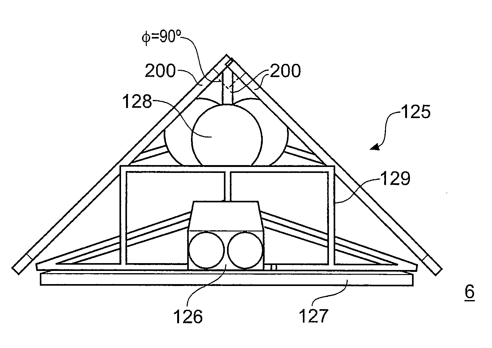
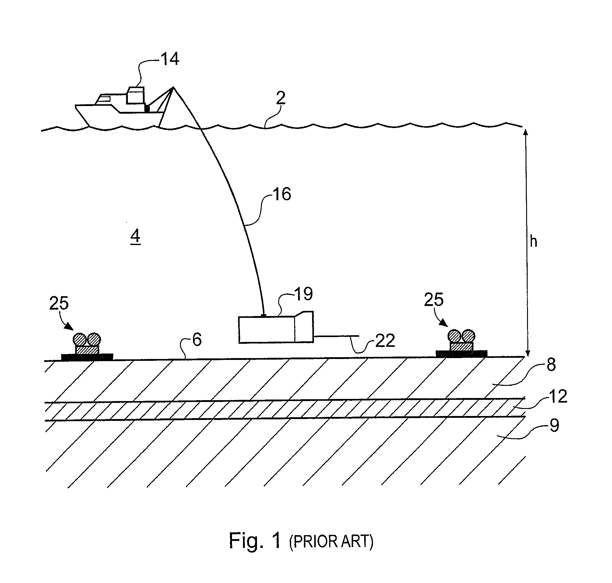
[0060]FIG. 4 schematically shows a surface vessel 14 undertaking controlled source electromagnetic (CSEM) surveying of a subterranean strata configuration using EM detectors 125 according to an embodiment of the invention. Features of FIG. 4 which are similar to and will be understood from corresponding features of FIG. 1 are indicated by the same reference number. Thus the surface vessel 14 floats on the surface 2 of a body of seawater 4 of depth h metres. A submersible vehicle 19 carrying a source in the form of an HED transmitter 22 is attached to the surface vessel 14 by an umbilical cable 16 providing an electrical and mechanical connection between the submersible vehicle 19 and the surface vessel 14. The HED transmitter is supplied with a drive current so that it broadcasts an HED EM signal into the seawater 4. The HED transmitter is typically around 50 metres above the seafloor 6. The surface vessel 14, submarine 19, umbilical 16 and HED transmitter 22 may be conventional.

[00...


PUM


Abstract

A detector for underwater electromagnetic surveying is described. The detector comprises first, second, third and fourth electrodes which are arranged to define first, second and third electric dipole antennae extending between pairs of the electrodes. Each dipole antennae extends between a pair of the electrodes and the fourth electrode is common to all three dipole antennae. Thus the first electrode is separated from the fourth electrode along a first direction to provide the first dipole antenna, the second electrode is separated from the fourth electrode along a second direction to provide the second dipole antenna, and the third electrode is separated from the fourth electrode along a third direction to provide the third dipole antenna. The electrodes are arranged so that the first, second and third directions are inclined at an angle of between 20 and 70 degrees to a surface on which the detector rests when in normal use.

Description

BACKGROUND OF THE INVENTION[0001]The invention relates to seafloor electromagnetic detectors (receivers) for surveying for resistive and / or conductive bodies, for example for oil and other hydrocarbon reserves, or subterranean salt bodies.[0002]FIG. 1 schematically shows a surface vessel 14 undertaking controlled source electromagnetic (CSEM) surveying of a subterranean strata configuration according to one standard technique [1]. The subterranean strata configuration in this example includes an overburden layer 8, an underburden layer 9 and a hydrocarbon reservoir 12. The surface vessel 14 floats on the surface 2 of a body of water, in this case seawater 4 of depth h metres. A submersible vehicle 19 carrying a source in the form of a horizontal electric dipole HED transmitter 22 is attached to the surface vessel 14 by an umbilical cable 16. This provides an electrical and mechanical connection between the submersible vehicle 19 and the surface vessel 14. The HED transmitter is supp...

Claims


Application Information

Patent Timeline
Patent Type & Authority Applications(United States)
IPC IPC(8): G01V3/12
CPCG01V3/083G01V3/12G01V3/082
Inventor MACGREGOR, LUCYPRATT, DAVID CHARLES NEWALLNICHOLLS, JONATHAN HARVEYSINHA, MARTIN C.
Owner OHM
Why Eureka
Try Eureka