
A thin tube sheath

A technology of thinning pipes and sheaths, which is applied in steam superheating, lighting and heating equipment, steam generation, etc., and can solve problems such as exposed wear of pipe rows, thermal expansion and deformation, etc.

Active Publication Date: 2021-07-06
ORDOS JUNZHENG ENERGY CHEM
View PDF5 Cites 0 Cited by
  • Summary
  • Abstract
  • Description
  • Claims
  • Application Information

AI Technical Summary

Problems solved by technology

[0004] The purpose of the present invention is to provide a strainer pipe sheath to solve the problem that the existing strainer pipe sheath is heated and expanded and deformed during operation, resulting in the exposed wear of the pipe row

Method used

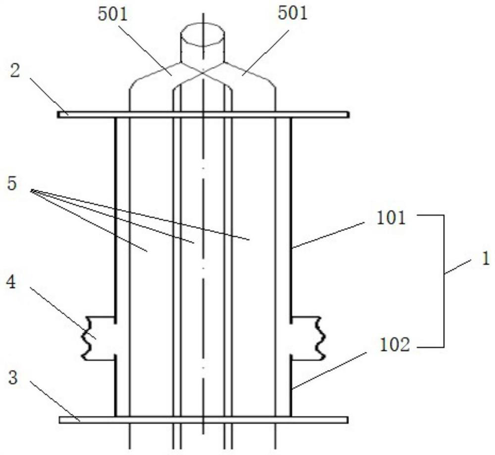

Image

  • A thin tube sheath
  • A thin tube sheath
  • A thin tube sheath

Examples


Embodiment Construction

[0023] In order to make the purpose, technical solutions and advantages of the embodiments of the present invention clearer, the technical solutions in the embodiments of the present invention will be clearly and completely described below in conjunction with the drawings in the embodiments of the present invention. Obviously, the described embodiments It is a part of embodiments of the present invention, but not all embodiments. Based on the embodiments of the present invention, all other embodiments obtained by persons of ordinary skill in the art without making creative efforts belong to the protection scope of the present invention.

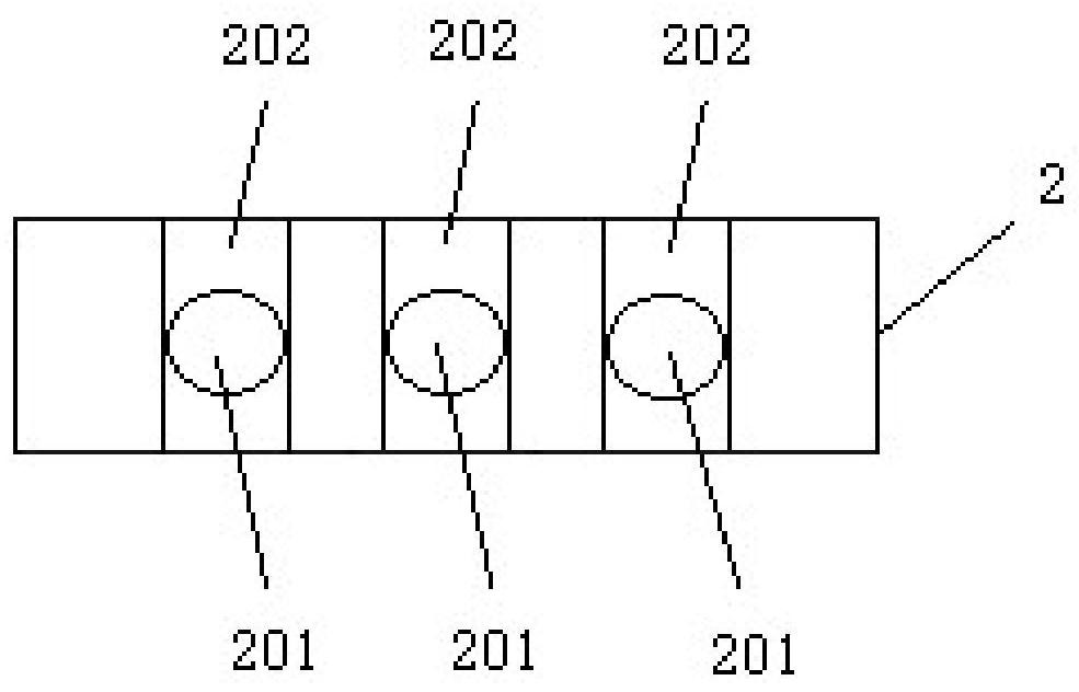
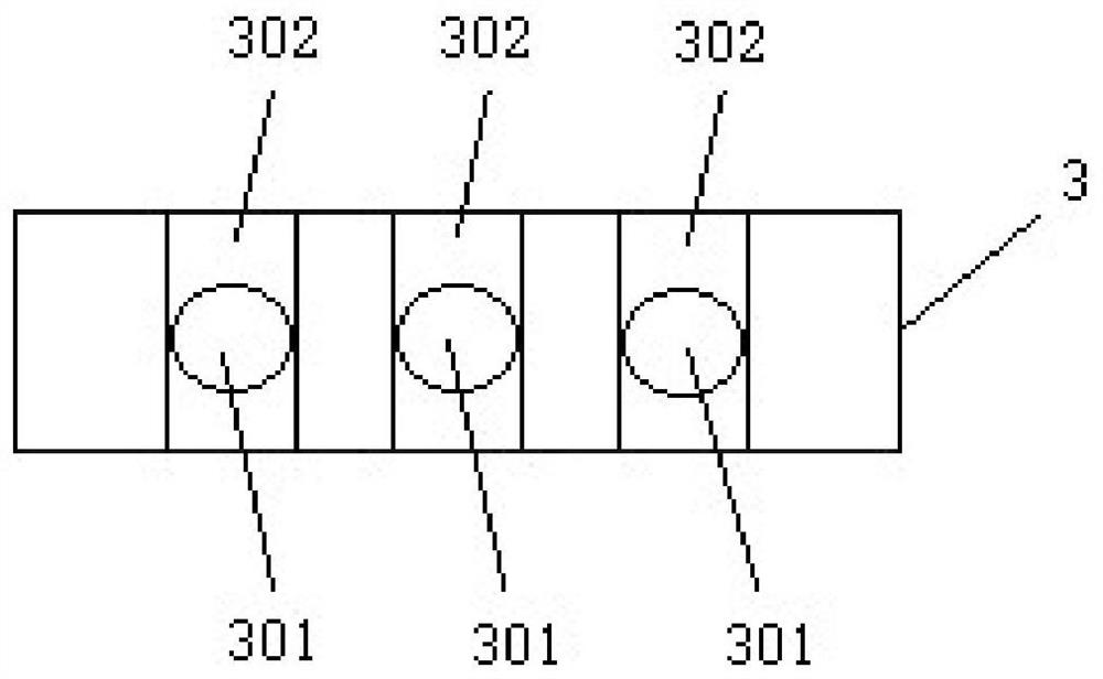
[0024] Such as Figure 1-3 As shown, the embodiment of the present invention provides a strainer sheath, including a sheath body 1, an upper mounting plate 2, a lower mounting plate 3 and a compensator 4.

[0025] The sheath body 1 is a cylindrical structure with upper and lower ends open, and the sheath body 1 is used to fit on the outside ...


PUM


Abstract

The invention relates to the technical field of thinning pipe protection, in particular to a thinning pipe sheath. The thinning tube sheath includes a sheath body, an upper mounting plate, a lower mounting plate and a compensator. The upper and lower ends of the sheath body are respectively connected to the upper mounting plate and the lower mounting plate. The compensator is sleeved on the upper and lower mounting plates. On the outside of the sheath body, the compensator divides the outer side wall of the sheath body into an upper section of the sheath body and a lower section of the sheath body. The thinning tube sheath provided by the invention has sufficient expansion margin when it is heated and expanded during the operation of the boiler, and can freely expand upward and downward along the compensator without encountering resistance, thereby effectively preventing deformation of the thinning tube sheath , so as to effectively avoid the problem of exposed wear and tear of the tube row, reduce the impact on the flue gas direction, and improve the stability of the boiler unit operation.

Description

technical field [0001] The invention relates to the technical field of strainer tube protection, in particular to a strainer tube sheath. Background technique [0002] The boiler tail wall superheater pulls thin tubes, which need to be protected by tube sheaths. The original pipe sheath structure is made by butting two U-shaped plates. However, the pipe sheath of this structure will be heated and expanded during the operation of the boiler and will be severely deformed, resulting in the exposure of the pipe row, affecting the direction and flow rate of the flue gas, causing serious wear and tear of the front cladding wall, and affecting the stability of the unit operation. sex. Contents of the invention [0003] (1) Technical problems to be solved [0004] The object of the present invention is to provide a strainer pipe sheath, which solves the problem that the existing strainer pipe sheath is thermally expanded and deformed during operation, resulting in exposed wear ...

Claims


Application Information

Patent Timeline
Patent Type & Authority Patents(China)
IPC IPC(8): F22G3/00
CPCF22G3/008
Inventor 王建军邢强李江徐震马兴能窦东官裴振全张龙张昊张鑫
Owner ORDOS JUNZHENG ENERGY CHEM
Learn More