Differential mode inductor-free staggered parallel Vienna rectifier and control circuit thereof

A technology of control circuit and inductance circuit, applied in the direction of converting AC power input to DC power output, electrical components, output power conversion devices, etc., can solve the problem of high total harmonic distortion, zero-crossing distortion, total harmonic The problem of high distortion rate can reduce the total harmonic distortion rate, reduce the output voltage ripple, and reduce the volume and weight.

Active Publication Date: 2019-11-26
连云港杰瑞电子有限公司
View PDF3 Cites 5 Cited by
  • Summary
  • Abstract
  • Description
  • Claims
  • Application Information

AI Technical Summary

Problems solved by technology

[0003] In the traditional Vienna rectifier, the presence of inductance and the delay effect of the current inductor will cause a small phase shift, resulting in zero-crossing distortion, resulting in an excessively high total harmonic distortion rate of the converter
In response to the above problems, the document "Xu H, YaoW, Shao S, et al. Improved SVPWM schemes for vienna rectifiers without current distortion [C]. european conference on cognitive ergonomics, 2017: 3410-3414." proposed to use the space vector pulse width modulation method , according to different current directions to determine the limit range of the vector, so as to select the appropriate vector, reduce the zero-crossing distortion, but because of the emphasis on control efficiency, the total harmonic distortion rate of the whole machine is still high

Method used


Image

  • Differential mode inductor-free staggered parallel Vienna rectifier and control circuit thereof
  • Differential mode inductor-free staggered parallel Vienna rectifier and control circuit thereof
  • Differential mode inductor-free staggered parallel Vienna rectifier and control circuit thereof

Examples


Embodiment 1

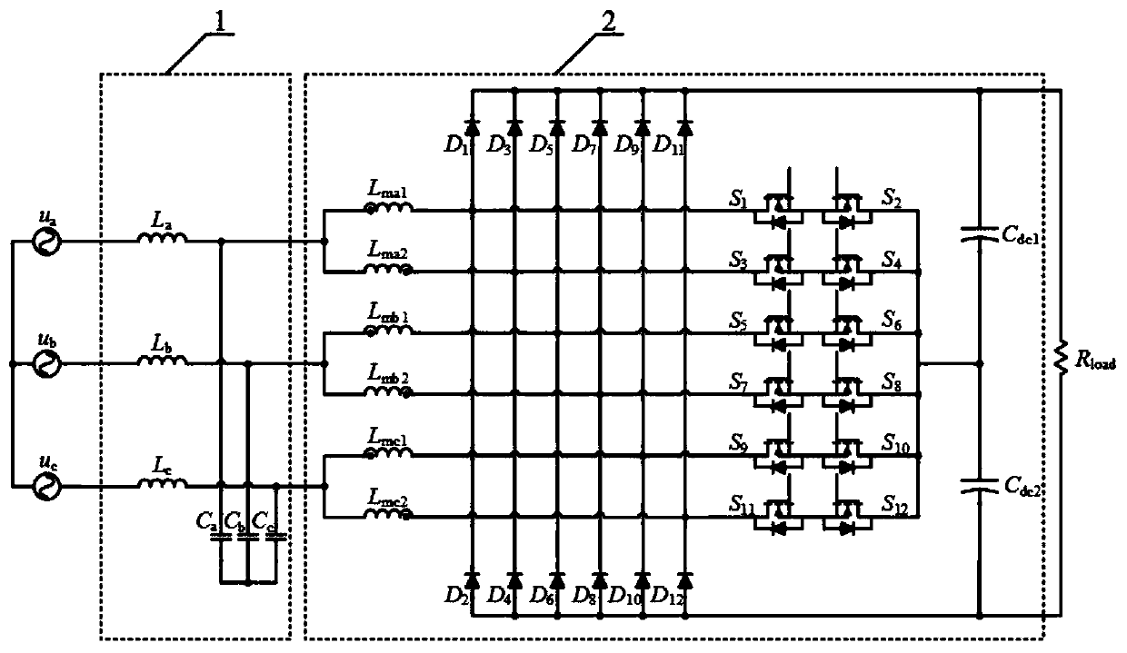
[0030] Embodiment 1, with reference to figure 1, an interleaved parallel Vienna rectifier without differential mode inductance, the rectifier includes a grid-side filter circuit and an interleaved parallel Vienna rectifier circuit connected in series between a three-phase input power supply and a load;

[0031] The grid-side filter circuit includes a first filter inductor La, a second filter inductor Lb, and a third filter inductor Lc connected in parallel to the three-phase input power supply, the output end of the first filter inductor La and the output end of the second filter inductor Lb The first filter capacitor Ca and the second filter capacitor Cb are connected in series, and the neutral point of the first filter capacitor Ca and the second filter capacitor Cb is connected to the output terminal of the third filter inductor Lc through the third filter capacitor Cc connected,

[0032] The interleaved parallel Vienna rectifier circuit includes three parallel inductance ...

Embodiment 2

[0060] Embodiment 2, the non-differential-mode inductance interleaved parallel Vienna rectifier described in embodiment 1, the grid-side filter circuit 1 only includes grid-side inductance.

Embodiment 3

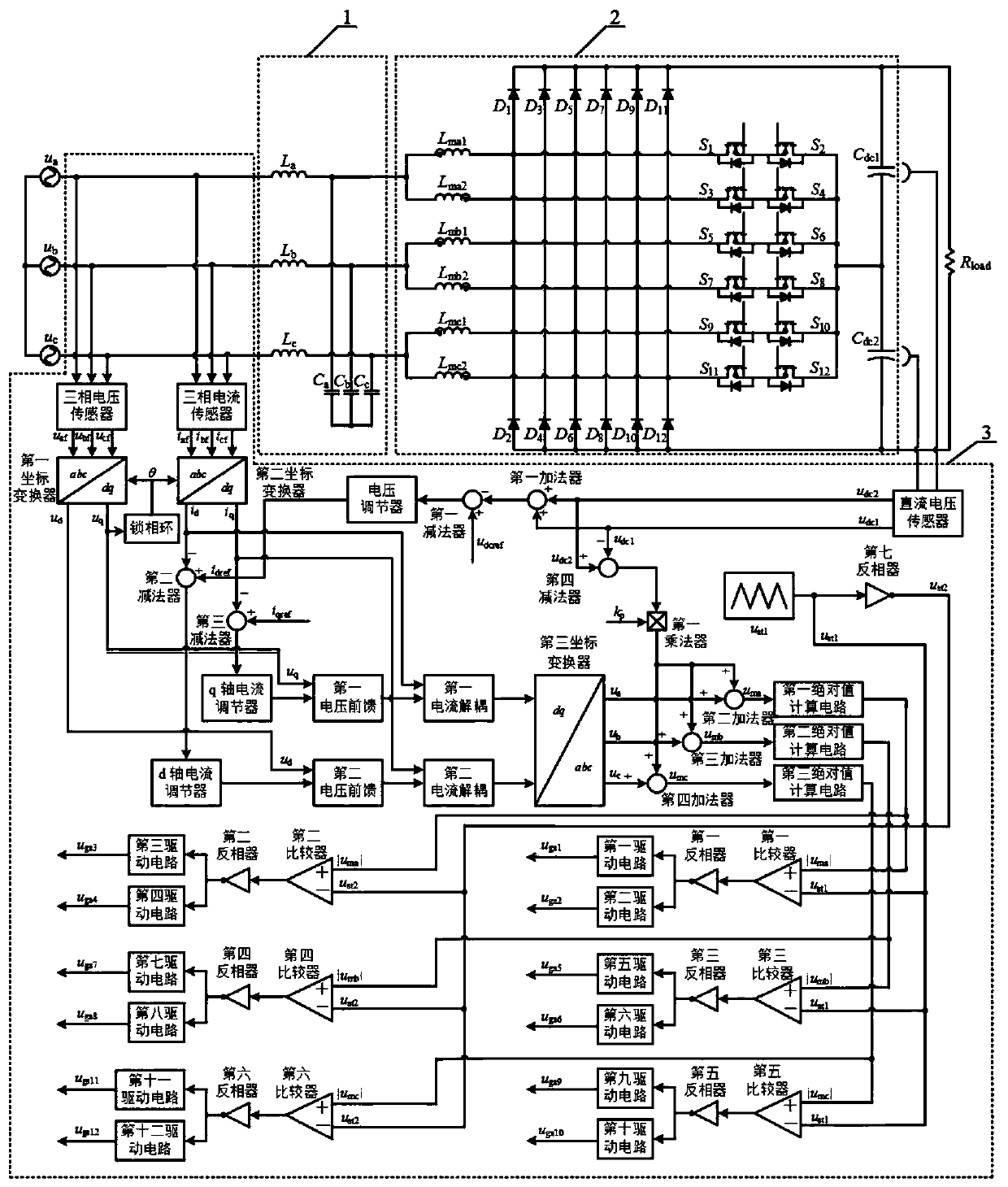
[0061] Embodiment 3, a control circuit of the Vienna rectifier described in Embodiment 1 and 2, the control circuit includes a three-phase voltage control circuit, a three-phase current control circuit and a DC voltage control circuit,

[0062]The three-phase voltage control circuit includes a three-phase voltage sensor for sampling the three-phase input power supply voltage, the three-phase voltage sensor is connected with a first coordinate converter, and the d-axis output terminal of the first coordinate converter passes through the second voltage before The feed is connected to the second current decoupling, the q-axis output terminal of the first coordinate transformer is connected to the first current decoupling through the first voltage feedforward, and the q-axis output terminal of the first coordinate transformer is also connected to a phase-locked loop, The output end of the phase-locked loop is respectively connected with an input end of the three-phase voltage senso...


PUM


Abstract

The invention relates to a differential mode inductor-free staggered parallel Vienna rectifier and a control circuit thereof. The rectifier comprises a network side filter circuit and a staggered parallel Vienna rectifier circuit, wherein the staggered parallel Vienna rectifier circuit comprises a three-phase coupling inductor, first to twelve power switch tubes, and first to twelve power diodes.The invention further discloses a control circuit of the rectifier. The network side filter circuit suppresses nearby harmonics of switch frequency; leakage inductance of the coupling inductor replaces differential mode inductance, so that volume and weight of a converter are lowered; the staggered parallel manner increases capacity of the converter, lowers current stress of the switch tube, and reduces input current ripples and output voltage ripples, thereby reducing capacitance of a bus capacitor and volume and weight of a magnetic element. The differential mode inductor-free staggered parallel Vienna rectifier has characteristics of low deformation rate of total harmonics, small volume and weight, small input current ripples and small output voltage ripples.

Description

technical field [0001] The invention belongs to the technical field of power electronic converter control, in particular to a Vienna rectifier with no differential mode inductance interlaced parallel connection and its control circuit. Background technique [0002] The rectifier circuit is a nonlinear topology, which will bring a lot of harmonics, causing a series of problems such as harmonic pollution and reactive power loss. At this stage, it is mainly improved from two aspects: one is to start from the power system itself, adding reactive power compensation devices and filters and other equipment on the grid side; the other is to improve the power factor correction performance of power electronic devices. Among them, the Vienna rectifier circuit, as a kind of power factor correction converter, is of great significance to improve harmonic pollution and reactive power loss due to its advantages of avoiding bridge arm direct connection and three-level clamping structure. ...

Claims


Application Information

Patent Timeline
Patent Type & Authority Applications(China)
IPC IPC(8): H02M7/217H02M1/12H02M1/14
CPCH02M1/12H02M1/14H02M7/2173
Inventor 王廷营王永生唐海瑞刘传亮桂飞王云财苏通曹广超袁涛朱民杰朱守伟朱培鸿钦梦玮孙宇
Owner 连云港杰瑞电子有限公司
Why Eureka
Try Eureka