A power mixer circuit

A mixer and circuit technology, which is applied in the field of multi-mode multi-frequency power mixer circuits, can solve the problems of occupying a large chip, high cost of power mixers, output impedance changes, etc., and achieve the goal of reducing area and power consumption Effect

Active Publication Date: 2020-07-28
SHENZHEN GRADUATE SCHOOL TSINGHUA UNIV
View PDF6 Cites 0 Cited by
  • Summary
  • Abstract
  • Description
  • Claims
  • Application Information

AI Technical Summary

Problems solved by technology

[0003] like figure 2 As shown, the traditional mixer adopts Gilbert structure, and the power amplifier adopts Class-AB (Class AB power amplifier) ​​mode. In the case of single frequency band, two inductors are needed; Inductor, occupying a large number of chips, high cost
At the same time, the traditional mixer-plus-power-amplifier architecture is suitable for relatively large output power. Under the condition of output power of several dBm, the power consumption of this architecture is large, and in the case of multi-mode and multi-frequency, a large number of switches need to be added. There will be loss, resulting in low efficiency
In addition, usually under large-signal working conditions, the drain of the MOS transistor will have a large voltage fluctuation, and the large voltage fluctuation will cause a large change in the output impedance, which will cause nonlinearity and make the final emission The output spectrum of the machine contains large in-band components, which cannot achieve high linearity
Therefore, the current power mixer has high cost, high power consumption and low linearity

Method used


Image

  • A power mixer circuit
  • A power mixer circuit
  • A power mixer circuit

Examples


Embodiment Construction

[0036] The embodiments of the present invention will be further described below in conjunction with the drawings and embodiments.

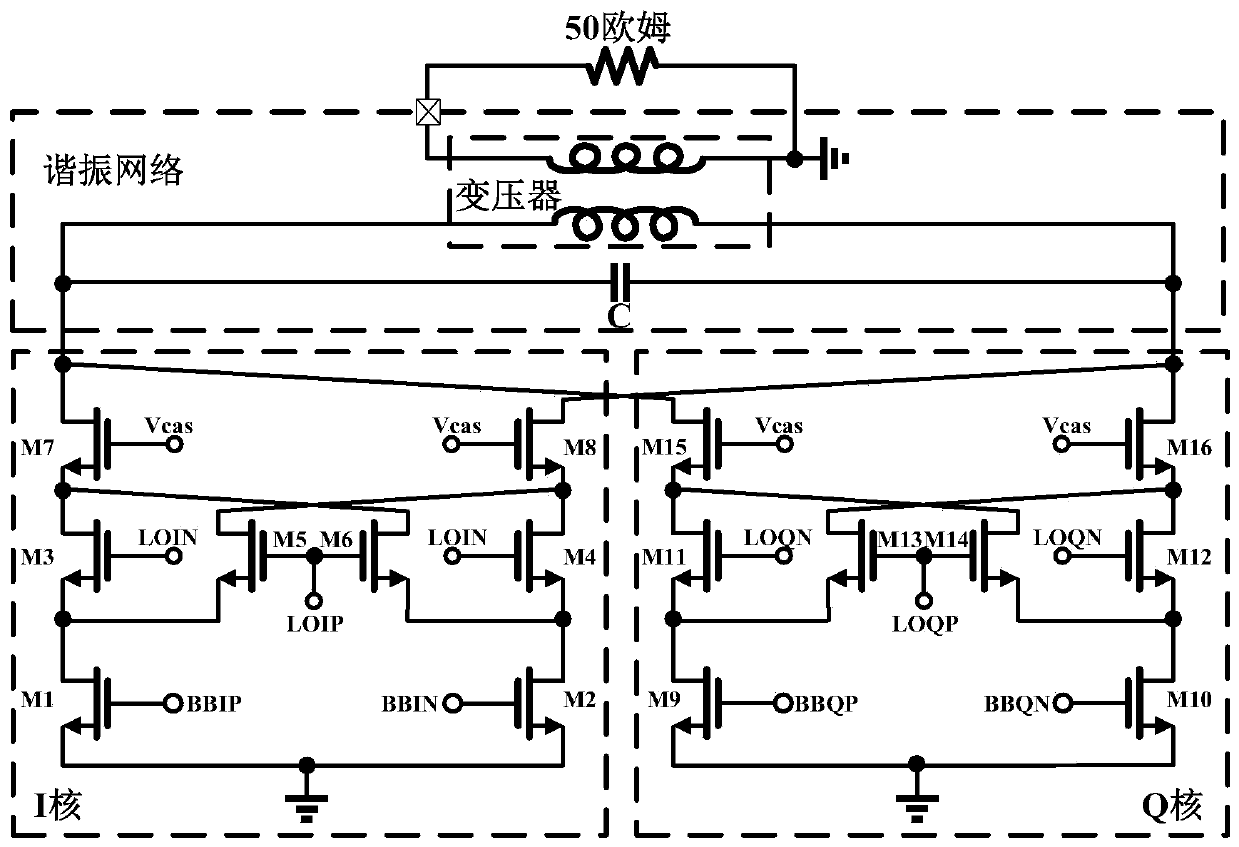
[0037] Such as image 3 As shown, the power mixer consists of two cores (I core and Q core in the figure) and a load composed of a resonant network. In the I core, transistor M1 and transistor M2 are pseudo-differential pairs composed of two MOS transistors as input transistors, which convert the input baseband voltage signals (BBIP, BBIN, BBQP, BBQN) into baseband current signals. In order to improve efficiency, transistor M1 1. Transistor M2 works in Class-AB (Class AB power amplifier) ​​state; transistors M3, M5 and transistors M4, M6 form two sets of differential pairs respectively, by applying differential local oscillator signals (LOIP, LOIN, LOQP, LOQN ), if the swing of the local oscillator signal is large enough (greater than the overdrive voltage of the differential pair), the differential pair is a current switch, and the output curren...


PUM


Abstract

A power mixer circuit. The circuit combines a Gilbert mixer circuit and a power amplifier circuit. The power mixer circuit comprises, sequentially electrically connected, a transconductance stage circuit, a gain bootstrap circuit, a switch stage circuit, and a load circuit. The transconductance stage circuit is used to input a baseband signal. The gain bootstrap circuit is used to stabilize the output voltage of the transconductance stage circuit. The switch stage circuit is used to control the switch of the switch stage circuit on the basis of a local oscillator signal, such that the switch performs a switching function. The load circuit is used to connect a load. Relative to the prior art, the present power mixer circuit has low power consumption, low costs, and high linearity.

Description

technical field [0001] The invention relates to the technical field of wireless communication, in particular to a multi-mode multi-frequency power mixer circuit. Background technique [0002] The traditional direct up-conversion multi-mode multi-frequency mixer and power amplifier circuit such as figure 1 Shown: After passing through the LPF (low-pass filter), the IQ two-way signal is directly up-converted with the local oscillator signal LOI and LOQ signal with a difference of 90 degrees, and then sent to the power amplifier (PA) after summing. The transmitter front ends for different modes or frequency bands are completely separated, such as figure 1 Mid-band (1) and Band (2). [0003] Such as figure 2 As shown, the traditional mixer adopts the Gilbert structure, and the power amplifier adopts the Class-AB (Class AB power amplifier) ​​mode. In the single-band case, two inductors are required; in the multi-band case, more inductors are required due to complete separatio...

Claims


Application Information

Patent Timeline
Patent Type & Authority Patents(China)
IPC IPC(8): H03D7/16
CPCH03D7/16
Inventor 冯海刚游晓东幸新鹏
Owner SHENZHEN GRADUATE SCHOOL TSINGHUA UNIV
Why Eureka
Try Eureka