Full-automatic shaft pressing machine

A press machine, fully automatic technology, applied in the direction of presses, manufacturing tools, etc., can solve the problems of manual press, inability to feed, easy to get stuck, etc., to avoid manual manual operation, increase work efficiency, and prevent mechanical blocking. dead effect

Pending Publication Date: 2019-12-06
广东华远电子科技有限公司
View PDF0 Cites 0 Cited by
  • Summary
  • Abstract
  • Description
  • Claims
  • Application Information

AI Technical Summary

Problems solved by technology

[0005] The purpose of this application is to at least solve one of the above-mentioned technical defects, especially the existing pressing machines that require manual loading during loading, cannot be loaded while pressing, and are prone to jamming during loading. question

Method used


Image

  • Full-automatic shaft pressing machine
  • Full-automatic shaft pressing machine
  • Full-automatic shaft pressing machine

Examples


Embodiment 1

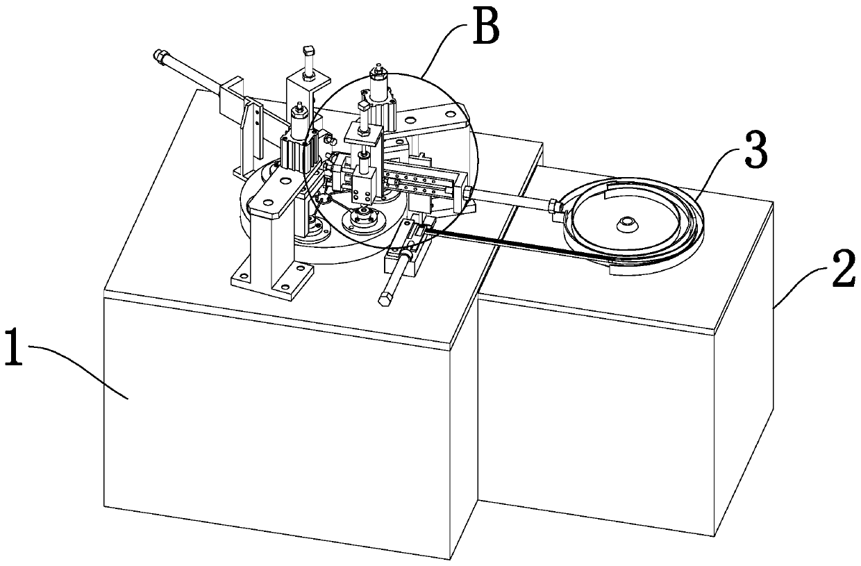
[0039] refer to figure 1 , figure 2 , image 3 As shown in the figure, a fully automatic pressing machine includes a pressing device 1 and a feeding device 2 fixedly connected to one side of the pressing device 1. A pressing mechanism 4 is arranged above the pressing device 1, and a pressing device 4 is arranged above the feeding device 2. There is a rotating device 3 .

[0040] The material is carried out through the rotating device 3 on the upper surface of the feeding device 2. The material is rotated in the track 31 and enters the feeding pipe 32, and enters the feeding device 6 through the feeding pipe 32. After feeding through the feeding device 6, the material is Carry out pressing by pressing device 1 and output by discharging device 7 .

[0041] refer to figure 1 , figure 2 , image 3 As shown, the upper end surface of the rotating device 3 is spirally connected with a track 31, and one side of the track 31 is fixedly connected with a feed pipe 32. A feeding ...

Embodiment 2

[0047] refer to figure 1 , figure 2 , image 3 As shown in the figure, a fully automatic pressing machine includes a pressing device 1 and a feeding device 2 fixedly connected to one side of the pressing device 1. A pressing mechanism 4 is arranged above the pressing device 1, and a pressing device 4 is arranged above the feeding device 2. There is a rotating device 3 .

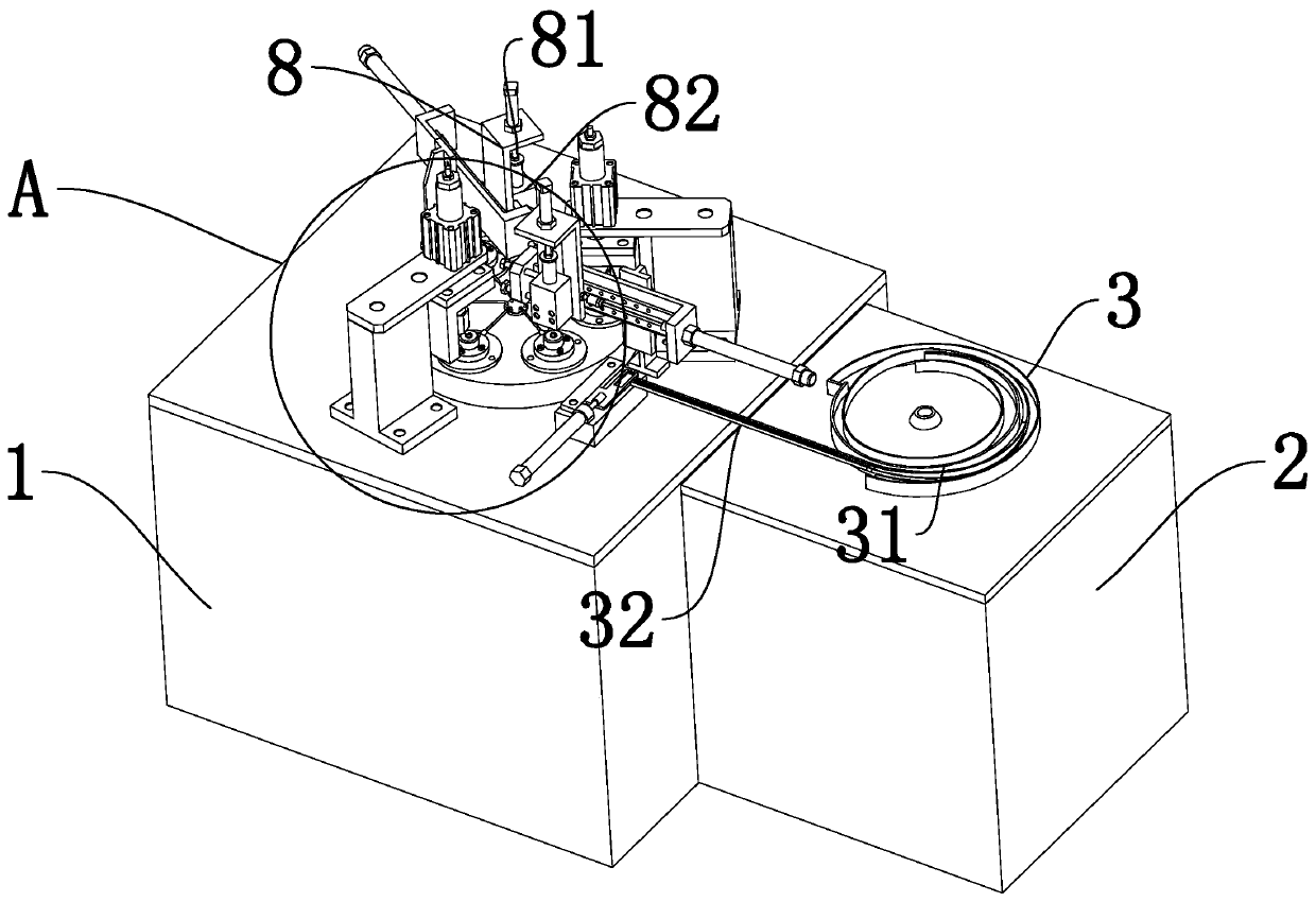
[0048] refer to figure 1 , figure 2 , image 3 As shown, the upper end surface of the rotating device 3 is spirally connected with a track 31, and one side of the track 31 is fixedly connected with a feed pipe 32. A feeding device 6 is provided on the side close to the feeding device 2 on the outside of the rotating device 3 , and the rotating device 3 is connected to the feeding device 6 through a feeding pipe 32 .

[0049] refer to figure 1 , figure 2 , image 3 , Figure 4 , Figure 5 , Figure 7 , Figure 8 As shown in , two symmetrically arranged pressing devices 43 are fixedly connected to...

Embodiment 3

[0058] refer to figure 1 , figure 2 , image 3 As shown in the figure, a fully automatic pressing machine includes a pressing device 1 and a feeding device 2 fixedly connected to one side of the pressing device 1. A pressing mechanism 4 is arranged above the pressing device 1, and a pressing device 4 is arranged above the feeding device 2. There is a rotating device 3 .

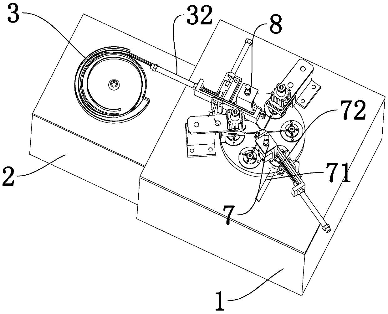
[0059] refer to figure 1 , figure 2 , image 3 As shown, the upper end surface of the rotating device 3 is spirally connected with a track 31, and one side of the track 31 is fixedly connected with a feed pipe 32. A feeding device 6 is provided on the side close to the feeding device 2 on the outside of the rotating device 3 , and the rotating device 3 is connected to the feeding device 6 through a feeding pipe 32 .

[0060] refer to figure 1 , figure 2 , image 3 , Figure 4 , Figure 5 , Figure 7 , Figure 8 As shown in , two symmetrically arranged pressing devices 43 are fixedly connected ...


PUM


Abstract

The invention discloses a full-automatic shaft pressing machine. The full-automatic shaft pressing machine comprises a pressing device and a feeding device, wherein the feeding device is fixedly connected with one side of the pressing device; a pressing mechanism is arranged at the upper portion of the pressing device; a rotating device is arranged at the upper portion of the feeding device; the upper end face of the rotating device is spirally connected with a rail; one side of the rail is fixedly connected with a feeding pipe; the pressing mechanism comprises a rotating plate which is fixedly connected with the upper end face of the pressing device; one side, close to the feeding device, of the outer side of the rotating plate is provided with a charging device; the rotating device is connected with the charging device through a charging pipe; the feeding device, the rotating device and the pressing mechanism are arranged in an integration manner so as to realize an automatic feedingfunction in a feeding process; manual operation is prevented; the work efficiency is improved; and mechanical chucking is prevented in the feeding process by arranging a first push shaft between thefeeding device and the rotating device.

Description

technical field [0001] The present application relates to the technical field of vehicle charging, in particular to a fully automatic pressing machine. Background technique [0002] Pressing machine is used to press the iron core into a mould; [0003] When the present pressing machine is carried out through the pressing mechanism, it is necessary to manually put the sheet material into the pressing mechanism for tablet pressing. [0004] The existing pressing machine needs to be manually loaded during the pressing, and cannot be loaded while pressing the pressing machine, and is easy to be stuck during loading. Contents of the invention [0005] The purpose of this application is to at least solve one of the above-mentioned technical defects, especially the existing pressing machines that require manual loading during loading, cannot be loaded while pressing, and are prone to jamming during loading. question. [0006] The present invention provides a fully automatic pr...

Claims


Application Information

Patent Timeline
Patent Type & Authority Applications(China)
IPC IPC(8): B30B15/30
CPCB30B15/30
Inventor 杨光宏宁永宏
Owner 广东华远电子科技有限公司
Why Eureka
Try Eureka