Anti-falling mechanism suitable for suspension type vertical fin dock

A vertical tail dock and suspension technology, applied in the field of anti-drop mechanism, can solve the problems of complicated riveting operation process and safety accidents, and achieve the effect of avoiding locking operation process, ensuring safety and avoiding instantaneous impact force

Pending Publication Date: 2019-12-10
SHENYANG BAOTONG DOOR
View PDF0 Cites 2 Cited by
  • Summary
  • Abstract
  • Description
  • Claims
  • Application Information

AI Technical Summary

Problems solved by technology

[0003] At present, the traditional anti-fall mechanism is generally a steel wire riveting structure. Every time the position of the vertical tail dock is adjusted, the steel wire rope needs to be riveted again, resulting in a complicated riveting operation process. In order to ensure that the anti-fall mechanism has certain activities The steel wire rope after riveting needs to maintain a certain slack state. Once the vertical tail dock falls, the loose steel wire rope will be quickly tightened when the vertical tail dock falls, and the impact force when the vertical tail dock falls will instantly act on the vertical tail. On the hoisting mechanism of the vertical tail dock, if the instantaneous impact force exceeds the load limit of the hoisting mechanism of the vertical stern dock, serious safety accidents are likely to occur

Method used


Image

  • Anti-falling mechanism suitable for suspension type vertical fin dock
  • Anti-falling mechanism suitable for suspension type vertical fin dock
  • Anti-falling mechanism suitable for suspension type vertical fin dock

Examples


Embodiment Construction

[0016] The present invention will be further described in detail below in conjunction with the accompanying drawings and specific embodiments.

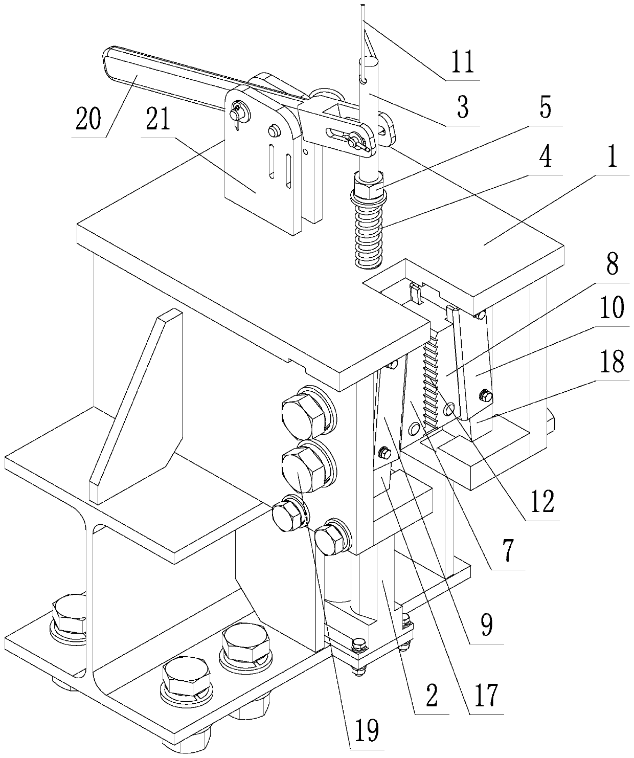
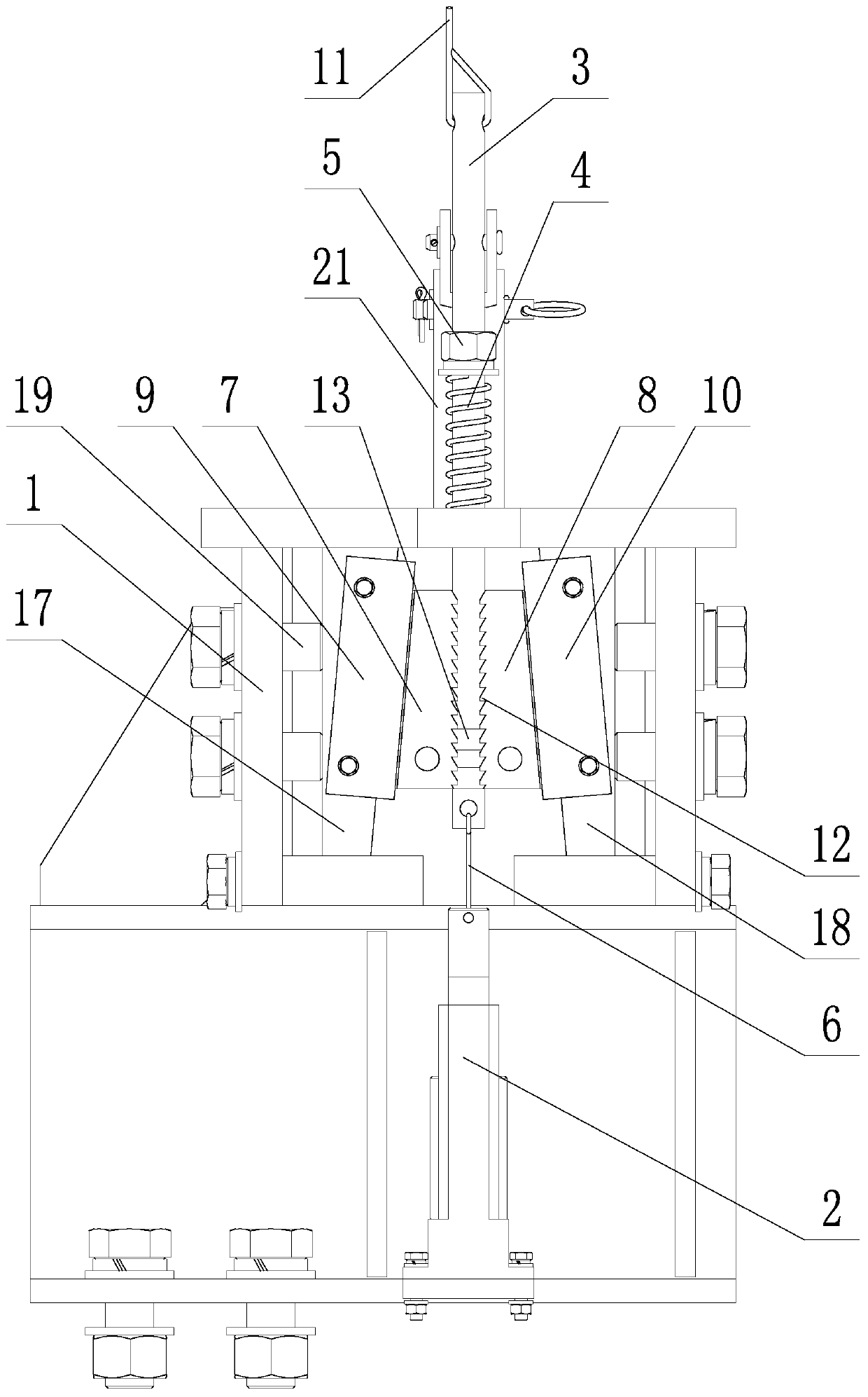
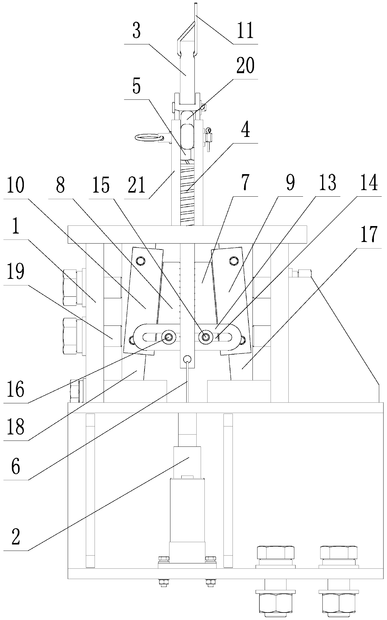
[0017] like Figure 1-3 As shown, an anti-drop mechanism suitable for a suspended vertical tail dock includes a frame 1, an electric push rod 2, a pull rod 3, a thrust spring 4, a limit nut 5, a safety rope 6, and the first slider chuck 7. The second slider chuck 8, the first guide rail base 9 and the second guide rail base 10; the frame 1 is fixed on the main frame of the vertical tail dock, and the electric push rod 2 is vertically fixed on the The lower part of the frame 1 is provided with a tie rod penetration hole on the top wall of the frame 1. The pull rod 3 passes through the pull rod penetration hole vertically. The pull rod 3 coincides with the central axis of the electric push rod 2, and the lower end of the pull rod 3 passes The safety rope 6 is connected with the electric push rod 2, and the upper end of the pull rod 3 i...


PUM


Abstract

Disclosed is an anti-falling mechanism suitable for a suspension type vertical fin dock. A rack is fixedly arranged on a main body frame of the vertical fin dock, the lower part of the rack is vertically and fixedly provided with an electric push rod, a pull rod vertically penetrates through a wall plate of the top of the rack, the pull rod is coaxial with the electric push rod, the lower end of the pull rod is connected with the electric push rod through a safety rope, the upper end of the pull rod is connected with a retractor through a steel wire rope, and the retractor is arranged on a movable hanging bracket; the pull rod, between a limiting nut and the top wall plate of the rack, is sleeved with a thrust spring; sliding block chucks and guide rail bases both adopt symmetrical mounting structures, each sliding block chuck can linearly move along the corresponding guide rail base, the sliding contact surface of each sliding block chuck and the corresponding guide rail base has an inclination angle relative to a horizontal plane, the two sliding block chucks are symmetrically distributed on the two sides of the movable hanging bracket of a hoisting mechanism of the vertical findock, the clamping surfaces of the two sliding block chucks are parallel, and the clamping surfaces of the sliding block chucks are provided with tooth-shaped grains; and a transmission rod is horizontally and fixedly arranged on the pull rod, a linear sliding groove is horizontally formed in the transmission rod, sliding pins are fixedly arranged on the sliding block chucks, and the sliding pinsare positioned in the linear sliding groove.

Description

technical field [0001] The invention belongs to the technical field of aircraft repair docks, in particular to an anti-fall mechanism suitable for a suspended vertical tail dock. Background technique [0002] The vertical tail dock is a platform used for the maintenance of the vertical tail of the aircraft. The existing vertical tail docks generally adopt a gantry-like structure, and the vertical tail dock is installed in a suspended manner as a whole. In the process of adjusting the overall position of the vertical tail dock, in order to To avoid falling accidents in the vertical tail dock, it is necessary to equip the vertical tail dock with a fall prevention mechanism. [0003] At present, the traditional anti-fall mechanism is generally a steel wire riveting structure. Every time the position of the vertical tail dock is adjusted, the steel wire rope needs to be riveted again, resulting in a complicated riveting operation process. In order to ensure that the anti-fall me...

Claims


Application Information

Patent Timeline
Patent Type & Authority Applications(China)
IPC IPC(8): B66C15/02B64F5/40
CPCB64F5/40B66C15/02
Inventor 杨元正孙宝峰张培勇陆喜郭宋姚红坚王兴徐忠关英玲
Owner SHENYANG BAOTONG DOOR
Why Eureka
Try Eureka