
Lamp control system

A control system and lighting technology, applied in the field of control systems, can solve the problems of large energy consumption, large gap between day and night, and rigid time control control methods, so as to save energy and prevent personal electric shock and electrical fires.

Pending Publication Date: 2019-12-10
中媒数字媒体(江苏)有限公司
View PDF10 Cites 0 Cited by
  • Summary
  • Abstract
  • Description
  • Claims
  • Application Information

AI Technical Summary

Problems solved by technology

[0002] At present, the billboard products all use a single time control to control the lighting. If you want to save energy, the lighting time of the billboard will be controlled. If you want to ensure long-term lighting, the energy consumption will be large and it will easily cause light pollution.
In addition, there is a large gap between day and night in winter and summer, and the independent time control method is rigid. It is necessary to ensure that the product is lit when it is dark in winter, so it will inevitably cause energy waste in summer.

Method used


Image

  • Lamp control system

Examples


Embodiment Construction

[0023] The present invention will be further described below in conjunction with accompanying drawing.

[0024] The following description is provided with reference to the accompanying drawings to facilitate a comprehensive understanding of various embodiments of the invention defined by the claims. It contains various specific details to facilitate that understanding but these should be regarded as merely exemplary. Accordingly, those of ordinary skill in the art will recognize that changes and modifications of the various embodiments described herein can be made without departing from the scope of the invention as defined in the appended claims. Also, descriptions of well-known functions and constructions may be omitted for clarity and conciseness.

[0025] Unless otherwise defined, all terms (including technical terms and scientific terms) used herein have the same meaning as commonly understood by one of ordinary skill in the technical field to which this application belo...


PUM


Abstract

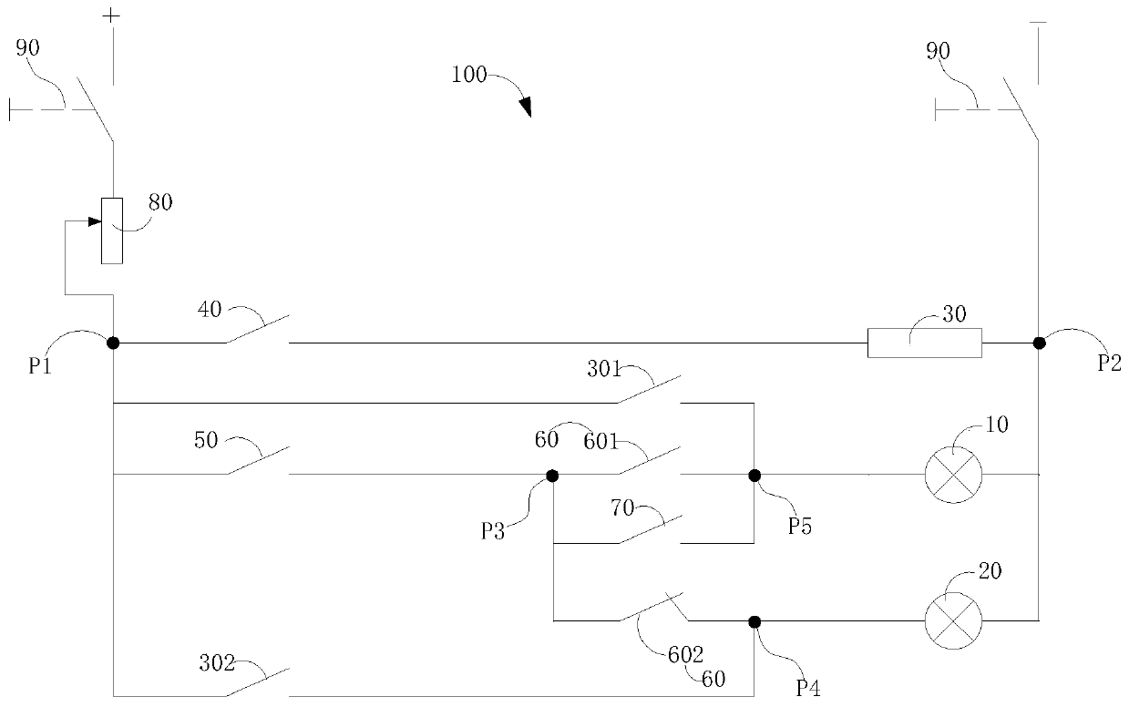
The invention discloses a lamp control system. The system comprises an intermediate relay configured to be coupled between an input voltage terminal and an output voltage terminal, a first lamp configured to be connected to two sides of the intermediate relay in parallel, a second lamp configured to be connected with the first lamp in parallel, a first relay normally open node, a second relay normally open node, a first time controller, a second time controller, a selected switch normally open node and a selected switch normally closed node, wherein one end of the second lamp is coupled between a first node and the first lamp, and the other end of the second lamp is coupled with a second node; one end of the first relay normally open node is coupled with the first node, and the other end is coupled between a third node and the second lamp; one end of the second relay normally open node is coupled with the first node, and the other end is coupled between the third node and the first lamp; the first time controller is coupled between the first node and the intermediate relay; the second time controller is coupled between the first node and the third node; a selected switch normally open node is coupled between the third node and the fifth node; and the selected switch normally closed node is coupled between the third node and a fourth node.

Description

technical field [0001] The invention relates to the field of control systems, in particular to a lamp control system. Background technique [0002] At present, billboard products all use a single time control to control the lighting. If you want to save energy, the lighting time of the billboard is controlled. If you want to ensure long-term lighting, it will consume a lot of energy and easily cause light pollution. In addition, there is a large gap between day and night in winter and summer, and the independent time control method is rigid. It is necessary to ensure that the product is lit when it is dark in winter, so it will inevitably cause energy waste in summer. Contents of the invention [0003] The present invention aims to solve one of the problems in the above-mentioned prior art, and proposes a lamp control system, which is flexible and convenient to control, energy-saving, environment-friendly, high in reliability and simple in structure. [0004] In order to ...

Claims


Application Information

Patent Timeline
Patent Type & Authority Applications(China)
IPC IPC(8): H05B37/02G09F13/00
CPCG09F13/005Y02B20/40
Inventor 冯玉林
Owner 中媒数字媒体(江苏)有限公司
Learn More