Optical imaging lens

An optical imaging lens and lens technology, applied in the field of lenses, can solve the problems of small image area, many lenses, blue-violet fringing, etc., and achieve the effect of large image area and good infrared confocality

Pending Publication Date: 2019-12-13
XIAMEN LEADING OPTICS
View PDF0 Cites 3 Cited by
  • Summary
  • Abstract
  • Description
  • Claims
  • Application Information

AI Technical Summary

Problems solved by technology

For optical imaging lenses used in security monitoring and other fields, because they need to be used day and night, they are required to have better infrared confocal performance, but the existing optical imaging lenses with better infrared confocal performance need to take into account more wavelengths. , leading to serious blue-purple fringing phenomenon; in order to optimize the image quality, there are many lenses, resulting in a longer optical total length, and due to the relatively high image quality requirements, the image surface is generally small, which can no longer meet the increasing requirements

Method used


Image

  • Optical imaging lens
  • Optical imaging lens
  • Optical imaging lens

Examples


Embodiment 2

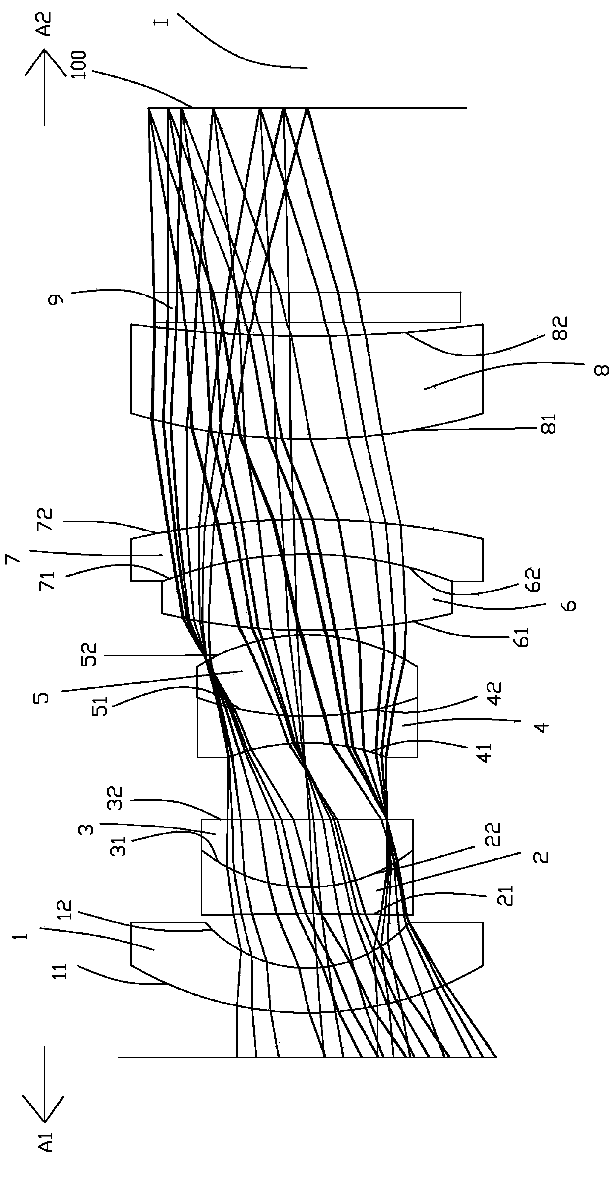
[0091] Such as Figure 8 As can be seen, the concave-convex surface and refractive index of each lens in this embodiment and the first embodiment are the same, and only the optical parameters such as the radius of curvature of the lens surface and the thickness of the lens are different.

[0092] The detailed optical data of this specific embodiment are shown in Table 2-1.

[0093] Detailed optical data of Table 2-1 Example 2

[0094] surface Diameter (mm) Radius of curvature (mm) Thickness (mm) material Refractive index Dispersion coefficient focal length(mm) - subject surface Infinity Infinity 11 first lens 8.000 7.793 0.900 H-KF6 1.52 52.19 -10.58 12 4.623 3.098 1.215 21 second lens 4.531 -70.125 0.600 H-K9L 1.52 64.21 -7.01 22 4.800 3.848 0 31 third lens 4.800 3.848 1.540 TAFD25 1.90 31.32 4.23 32 4.800 Infinity 0.000 - aperture ...

Embodiment 3

[0099] Such as Figure 15 As can be seen, the concave-convex surface and refractive index of each lens in this embodiment and the first embodiment are the same, and only the optical parameters such as the radius of curvature of the lens surface and the thickness of the lens are different.

[0100] The detailed optical data of this specific embodiment are shown in Table 3-1.

[0101] Detailed optical data of the third embodiment of table 3-1

[0102] surface Diameter (mm) Radius of curvature (mm) Thickness (mm) material Refractive index Dispersion coefficient focal length(mm) - subject surface Infinity Infinity 11 first lens 5.336 6.260 0.600 H-QK3L 1.49 70.42 -14.18 12 4.332 3.187 1.240 21 second lens 4.135 -27.593 0.600 H-K9L 1.52 64.21 -6.09 22 4.181 3.597 0 31 third lens 4.181 3.597 1.230 H-ZLAF75A 1.90 31.32 3.95 32 3.757 Infinity 0.298 ...

Embodiment 4

[0107] Such as Figure 22 As can be seen, the concave-convex surface and refractive index of each lens in this embodiment and the first embodiment are the same, and only the optical parameters such as the radius of curvature of the lens surface and the thickness of the lens are different.

[0108] The detailed optical data of this specific embodiment are shown in Table 4-1.

[0109] Table 4-1 Detailed optical data of Example 4

[0110] surface Diameter (mm) Radius of curvature (mm) Thickness (mm) material Refractive index Dispersion coefficient focal length(mm) - subject surface Infinity Infinity 11 first lens 8.000 8.146 1.061 H-KF6 1.52 52.19 -10.34 12 4.510 3.095 1.124 21 second lens 4.426 -72.013 0.600 H-K9L 1.52 64.21 -6.61 22 31 third lens 3.990 3.611 1.625 TAFD25 1.90 31.32 3.97 32 3.458 Infinity -0.013 - aperture 3.459 ...


PUM


Abstract

The invention belongs to the technical field of lenses and relates to an optical imaging lens. The invention discloses an optical imaging lens. The optical imaging lens comprises a first lens, a second lens, a third lens, a diaphragm, a fourth lens, a fifth lens, a sixth lens, a seventh lens and an eighth lens which are sequentially distributed from an object side to an image side along an opticalaxis; the first lens is a convex-concave lens with a negative refractive index; the second lens is a concave-concave lens with a negative refractive index; the third lens has a positive refractive index; the object side surface of the third lens is a convex surface; the fourth lens is a concave-concave lens with a negative refractive index; the fifth lens is a convex-convex lens with a positive refractive index; the sixth lens is a convex-convex lens with a positive refractive index; the seventh lens is a concave-convex lens with a negative refractive index; the eighth lens is a convex-concave lens with a positive refractive index; the second lens and the third lens are glued together; the fourth lens and the fifth lens are glued together; and the sixth lens and the seventh lens are gluedtogether. The optical imaging lens has the advantages of large image surface, good image quality, small infrared defocusing, small long in total length and unobvious blue-violet edge phenomena.

Description

technical field [0001] The invention belongs to the field of lens technology, in particular to an optical imaging lens. Background technique [0002] With the continuous advancement of technology, optical imaging lenses have also developed rapidly in recent years, and are widely used in various fields such as smart phones, tablet computers, video conferencing, vehicle monitoring, security monitoring, etc. Therefore, the requirements for optical imaging lenses are also Higher and higher. For optical imaging lenses used in security monitoring and other fields, because they need to be used day and night, they are required to have better infrared confocal performance, but the existing optical imaging lenses with better infrared confocal performance need to take into account more wavelengths. , resulting in serious blue-purple fringing; in order to optimize the image quality, there are many lenses, resulting in a longer optical total length, and due to the relatively high image ...

Claims


Application Information

Patent Timeline
Patent Type & Authority Applications(China)
IPC IPC(8): G02B13/00G02B13/14
CPCG02B13/0015G02B13/006G02B13/008G02B13/14
Inventor 曹来书王世昌
Owner XIAMEN LEADING OPTICS
Why Eureka
Try Eureka