Eureka AIR delivers breakthrough ideas for toughest innovation challenges, trusted by R&D personnel around the world.

Cable Suspension Lock and Its Matching Knot Hanger

A knot hanger and suspension technology, which is applied in the field of knot hangers, can solve the problems of inconvenient carrying, scattered, high work intensity and risk factor, etc., and achieve the effects of easy carrying, improved safety factor, and no need to move

Active Publication Date: 2020-08-04
赵琳萱
View PDF5 Cites 0 Cited by
  • Summary
  • Abstract
  • Description
  • Claims
  • Application Information

AI Technical Summary

Problems solved by technology

[0002] Cable is a general term for optical cables, wires and other items. Now the wires and cables in rural areas are the same as those in cities. They belong to power supply bureaus, telecommunications, mobile, China Unicom, radio and television and other departments. The wires between two adjacent houses and the communication cables across the intersection; multiple cables in the same direction are fixed on the reserved steel wire ropes, and the cables installed later, such as network cables and telephone cables, are scattered in the air in an arc shape. It affects the appearance of the city and the village; the existing technology mostly adopts the method of binding wires to solve this problem, and the staff need to use climbing ladders, lift trucks, etc. to bind the adjacent relatively loose cables with the originally reserved steel wire ropes Together, it brings higher work intensity and risk factor to the staff, and it is inconvenient to carry, and the cable management effect of all existing technologies is very poor

Method used


Image

  • Cable Suspension Lock and Its Matching Knot Hanger
  • Cable Suspension Lock and Its Matching Knot Hanger
  • Cable Suspension Lock and Its Matching Knot Hanger

Examples


Embodiment Construction

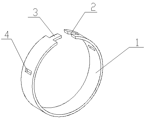
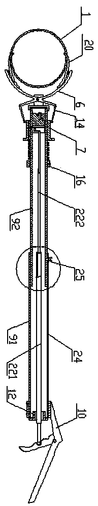
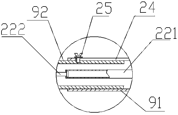
[0020] refer to Figure 1-6 , a cable suspension lock and its supporting knotter, the cable suspension lock includes a circular buckle 1, one end of the buckle 1 is provided with a groove 2, and the other end is provided with a strip-shaped convex 3, the groove 2 on the buckle cooperates with the strip-shaped protrusion 3 and is locked by its own elastic force. The gap formed by the docking of the groove 2 and the strip-shaped protrusion 3 is the self-locking mouth of the buckle, and the buckle The peripheral side of 1 is located at the two ends of the self-locking opening, and an expansion hole 4 is respectively arranged, and a layer of rubber pad 5 is fixed on the inner surface of the buckle ring 1, and a through hole is left on the rubber pad 5 corresponding to the expansion hole 4; The connector includes an expansion clip 6, a positioning cylinder 7, a locking pin 8, a handle 9 and a handle 10, the handle 9 is a hollow rod, the upper port of the handle is screwed to a cap ...


PUM


Abstract

The invention discloses a cable suspension lock catch and a matching knot hanger thereof. The lock catch comprises a circular buckle ring. A groove is arranged at one end of the buckle ring. The otherend is provided with a strip-shaped protrusion. The groove on the buckle ring is matched with the strip-shaped protrusion and locked by its own elastic force. The circumferential side surface of thebuckle ring is respectively provided with an expanding support hole located at the two ends of a self-locking port. The knot hanger comprises an expanding support clamp, a positioning cylinder, a locking pin, a hand-held rod and a handle. The hand-held rod is a hollow rod. A cap is screwed on the upper port of the hand-held rod. Two supporting ears with ear holes are fixed on the upper end of thecap. The clamping opening section of the clamp body is provided with a connector adapted to the expanding support hole. The positioning cylinder also sleeves on the hand-held rod. The locking pin is arranged in the inner cavity of the hand-held rod and a pulling piece for controlling the movement of the locking pin. The scattered or arc-shaped cables suspended in mid-air are enabled to be quicklyand safely bundled together so that the safety factor of workers during construction can be improved and the lock catch and the matching knot hanger can be operated by one person and thus time and labor can be saved.

Description

technical field [0001] The invention relates to the technical field of cable bundling, in particular to a cable suspension lock and a matching knotter. Background technique [0002] Cable is a general term for optical cables, wires and other items. Now the wires and cables in rural areas are the same as those in cities. They belong to power supply bureaus, telecommunications, mobile, China Unicom, radio and television and other departments. The wires between two adjacent houses and the communication cables across the intersection; multiple cables in the same direction are fixed on the reserved steel wire ropes, and the cables installed later, such as network cables and telephone cables, are scattered in the air in an arc shape. It affects the appearance of the city and the village; the existing technology mostly adopts the method of binding wires to solve this problem, and the staff need to use climbing ladders, lift trucks, etc. to bind the adjacent relatively loose cables ...

Claims


Application Information

Patent Timeline
Patent Type & Authority Patents(China)
IPC IPC(8): H02G7/05H02G1/04G02B6/46G02B6/48
CPCG02B6/46G02B6/483H02G1/04H02G7/05
Inventor 赵琳萱
Owner 赵琳萱
Why Eureka
Eureka Blog
Learn More