Bionic amphibious propeller

A propeller and bionic technology, applied in amphibious vehicles, motor vehicles, transportation and packaging, etc., can solve the problems of inability to take into account the needs of water and land, inconvenient operation and maintenance, complex structure, etc., and achieve broad practical The effect of application prospect, good adaptability and concise structure

Pending Publication Date: 2019-12-24
HARBIN ENG UNIV
View PDF6 Cites 5 Cited by
  • Summary
  • Abstract
  • Description
  • Claims
  • Application Information

AI Technical Summary

Problems solved by technology

Traditional amphibious propellers are generally a combination of water and land propellers. The overall structure is complex and inconvenient to operate and maintain. Amphibious equipment such as hovercraft is propelled by a single air paddle; amphibious vehicles use wheels and Two sets of water jet propulsion
These existing forms of amphibious propulsion cannot well balance the needs of the water surface and land

Method used


Image

  • Bionic amphibious propeller
  • Bionic amphibious propeller
  • Bionic amphibious propeller

Examples


Embodiment 1

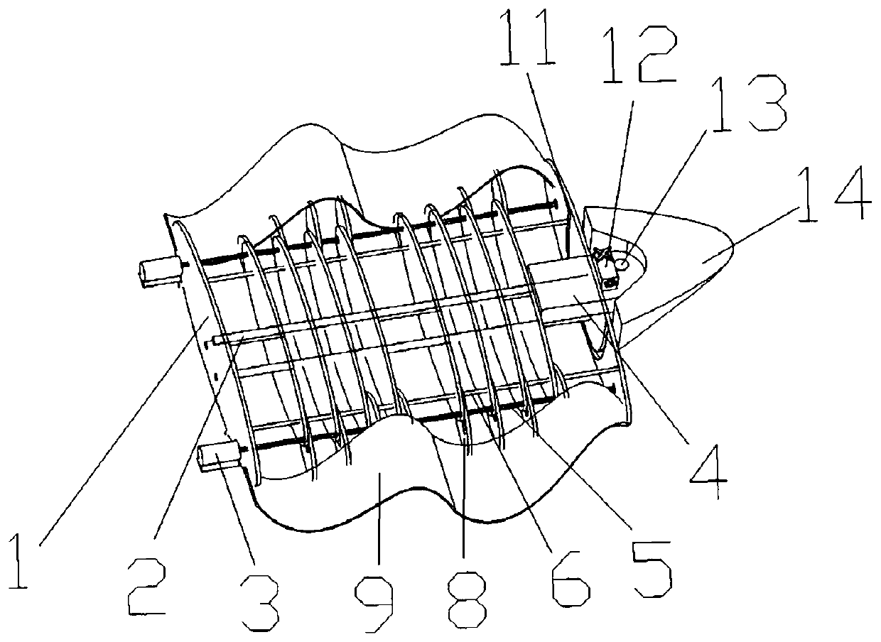
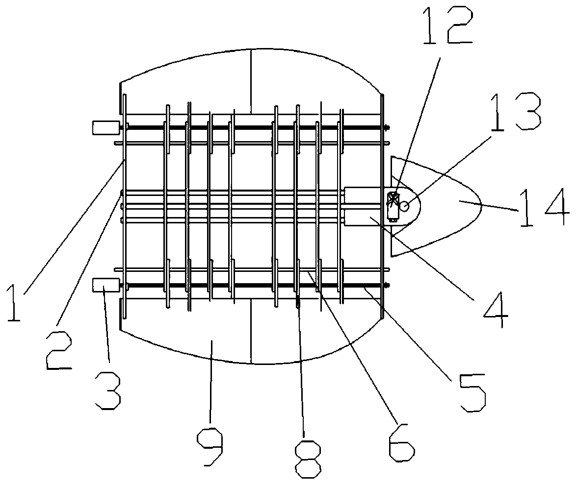
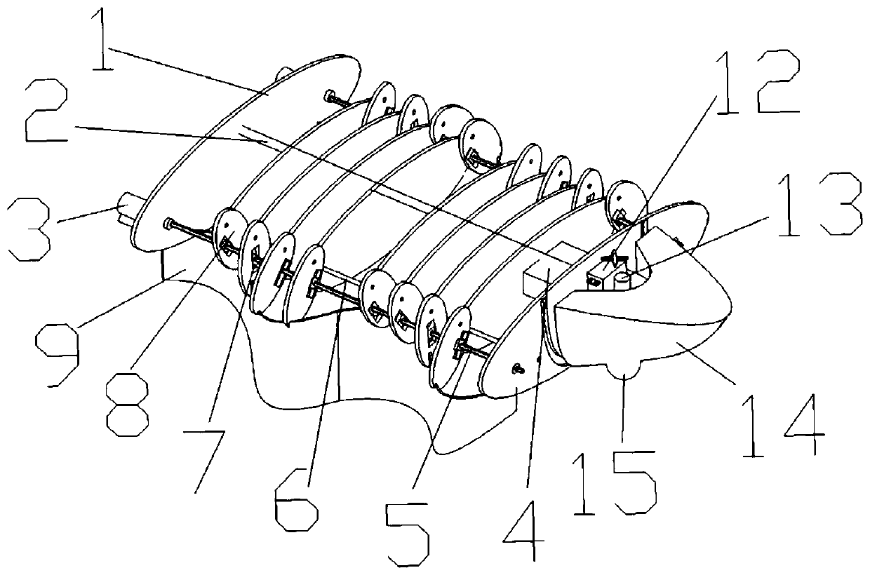
[0023] like Figure 1 to Figure 7 As shown, there are 8 middle ribs between the head rib and the tail rib, which can be called the first rib to the tenth rib from the beginning to the end, and the ten ribs are connected by 3 intermediate connecting rods , the distance between the ribs remains fixed, and the distance between the first rib and the second rib, the fifth rib and the sixth rib, the ninth rib and the tenth rib are the same and are other adjacent ribs Twice the distance between the plates. The phase differences of the eccentric wheels from the first rib to the tenth rib are respectively 0°, 120°, 180°, 240°, 300°, 60°, 120°, 180°, 240°, and 0°. like Image 6 As shown, the eccentric shaft 5 is a prismatic shaft in this example.

[0024] A swing part and an eccentric wheel are respectively arranged on the left and right sides of each rib, and are not fixedly connected with the rib. The eccentric wheel is connected through a prismatic rotating shaft, and the swingin...


PUM


Abstract

The invention belongs to the technical field of amphibious propellers and specifically relates to a bionic amphibious propeller. According to the bionic amphibious propeller, by outputting rotation ofa motor as rotation of an eccentric wheel in a swinging part through transmission of an eccentric wheel rotating shaft, the swinging part is driven to swing in a plane in a reciprocating manner, eacheccentric wheel is placed according to a certain phase difference, and therefore, sinusoid-like fluctuation of a flexible fin is realized. According to the bionic amphibious propeller, by adjusting the angle of the bionic flexible fin, the bionic flexible fin is adjusted from underwater horizontal fluctuation motion to vertical fluctuation motion on the land; and when the fin is erect, the bionicamphibious propeller can be supported to realize amphibious propelling. A bionic head part can rotate around a head rotating part under the control of a steering engine; and therefore, the directionof the propeller during moving in the water can be controlled; as a steering wheel is mounted at the bottom of the bionic head part, the direction of the propeller can be adjusted on the land. According to the bionic amphibious propeller, by using one set of mechanism, water and land amphibious propelling is realized; and therefore, the structure is simple, the realization is easy, good adaption ability to the complicated environment is realized, and broad actual application prospect in the fields such as transportation is realized.

Description

technical field [0001] The invention belongs to the technical field of amphibious thrusters, in particular to a bionic amphibious thruster. Background technique [0002] With the development of ship engineering technology, people have gradually developed a variety of high-performance special ships. Among them, amphibious vehicles that can adapt to various complex environments have become the focus of attention. There are many key technologies for amphibious vehicles, one of which is the propeller. Traditional amphibious propellers are generally a combination of water and land propellers. The overall structure is complex and inconvenient to operate and maintain. Amphibious equipment such as hovercraft is propelled by a single air paddle; amphibious vehicles use wheels and Water jets propel both sets. These existing amphibious propulsion forms cannot well take into account the needs on the water surface and on land. For this reason, it is necessary to develop a new type of ...

Claims


Application Information

Patent Timeline
IPC IPC(8): B60F3/00
CPCB60F3/0007
Inventor 于凯颜培凯郭春雨胡健王超刘洋汪瑜玮
Owner HARBIN ENG UNIV
Why Eureka
Try Eureka