Fish food feeding and cleaning equipment
A technology for cleaning equipment and fish food, applied in the field of fish food feeding and cleaning equipment, can solve problems such as fish tank pollution and fish food waste
- Summary
- Abstract
- Description
- Claims
- Application Information
AI Technical Summary
Problems solved by technology
Method used
Image
Examples
specific Embodiment approach 1
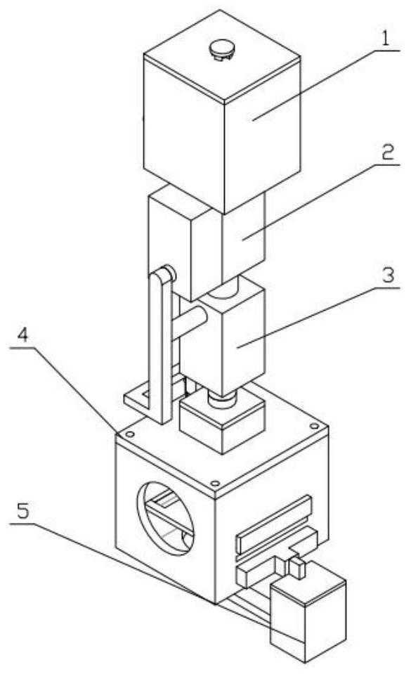
[0046] Combine below figure 1 , figure 2 , image 3 , Figure 4 , Figure 5 , Image 6 , Figure 7 , Figure 8 , Figure 9 , Figure 10 , Figure 11 , Figure 12 , Figure 13 , Figure 14 , Figure 15 , Figure 16 , Figure 17 , Figure 18 , Figure 19 , Figure 20 , Figure 21 , Figure 22 , Figure 23 , Figure 24 , Figure 25 , Figure 26 , Figure 27 Describe this embodiment mode, the present invention relates to a kind of sampling device, more specifically a kind of fish feed cleaning equipment, including storage box, control box, flushing box, feeding box, cleaning structure, the device can be stored and Stir the fish food and ventilate to prevent the fish food from being damp and deteriorated. The device can prevent the fish food from floating and cannot move down during the feeding process by washing the box. The feeding box and cleaning mechanism can evenly feed the fish food and filter and recycle the residue.
[0047] The bottom of the stor...
specific Embodiment approach 2
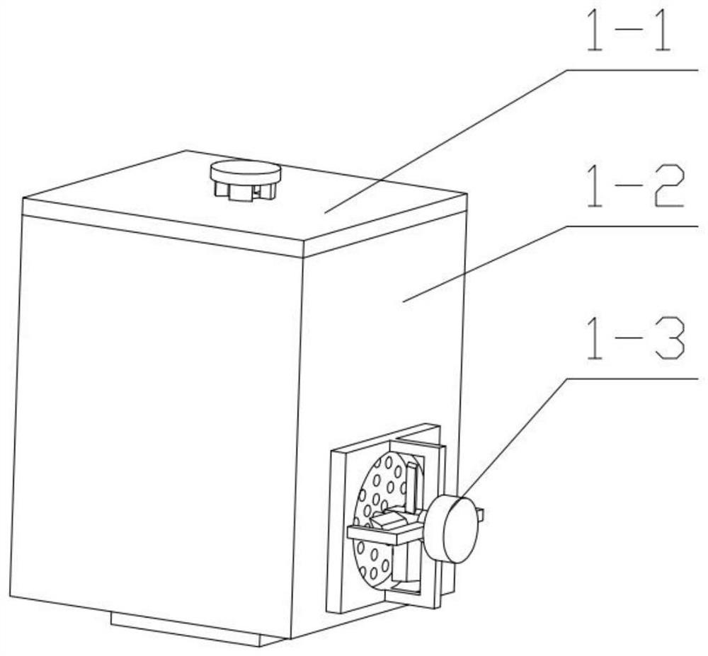
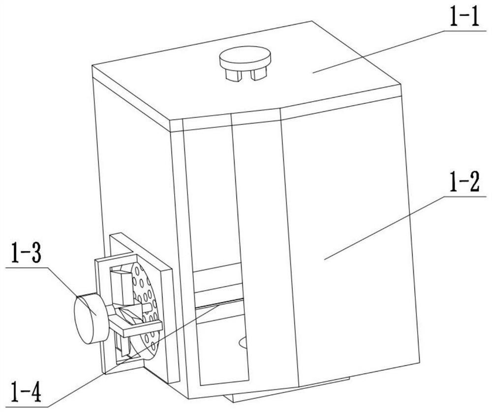
[0049] Combine below figure 1 , figure 2 , image 3 , Figure 4 , Figure 5 , Image 6 , Figure 7 , Figure 8 , Figure 9 , Figure 10 , Figure 11 , Figure 12 , Figure 13 , Figure 14 , Figure 15 , Figure 16 , Figure 17 , Figure 18 , Figure 19 , Figure 20 , Figure 21 , Figure 22 , Figure 23 , Figure 24 , Figure 25 , Figure 26 , Figure 27 Describe this embodiment, this embodiment will further explain the first embodiment, the storage box 1 includes a ventilation cover 1-1, a ventilation mixing box 1-2, a ventilation device 1-3, a mixing device 1-4, a ventilation cover 1 -1 is located on the upper part of the ventilation mixing box 1-2, the ventilation mixing box 1-2 is rectangular, one side of the ventilation mixing box 1-2 is processed with ventilation holes, and the ventilation device 1-3 is located on one side of the ventilation mixing box 1-2, The mixing device 1-4 is located inside the ventilation mixing box 1-2, and the mixing de...
specific Embodiment approach 3
[0051] Combine below figure 1 , figure 2 , image 3 , Figure 4 , Figure 5 , Image 6 , Figure 7 , Figure 8 , Figure 9 , Figure 10 , Figure 11 , Figure 12 , Figure 13 , Figure 14 , Figure 15 , Figure 16 , Figure 17 , Figure 18 , Figure 19 , Figure 20 , Figure 21 , Figure 22 , Figure 23 , Figure 24 , Figure 25 , Figure 26 , Figure 27 Describe this embodiment, this embodiment will further explain Embodiment 1, the control box 2 includes a hydraulic pressure cover 2-1, a multi-slot box 2-2, a control panel 2-3, and the hydraulic pressure cover 2-1 is located in multiple One side of the tank box 2-2, the upper part of the multi-tank box 2-2 is connected with the lower part of the storage box 1, the lower part of the multi-tank box 2-2 is connected with the flushing box 3, and the control panel 2-3 is located in the multi-tank box 2-2 Inside, the control panel 2-3 is located inside the water pressure cover 2-1; the water pressure cove...
PUM
 Abstract
Description
Claims
Application Information
 - R&D
- Intellectual Property
- Life Sciences
- Materials
- Tech Scout
- Unparalleled Data Quality
- Higher Quality Content
- 60% Fewer Hallucinations
Browse by: Latest US Patents, China's latest patents, Technical Efficacy Thesaurus, Application Domain, Technology Topic, Popular Technical Reports.
© 2025 PatSnap. All rights reserved.Legal|Privacy policy|Modern Slavery Act Transparency Statement|Sitemap|About US| Contact US: help@patsnap.com


