A bridge movable aerodynamic measure device and control method based on inertial vibration reduction

A technology of pneumatic measures and control methods, applied in bridges, bridge construction, bridge parts, etc., can solve the problems of immature movable pneumatic measures technology and inability to convert bridge engineering, so as to improve the overall wind resistance performance and reduce the vibration amplitude. Effect

Active Publication Date: 2020-12-29
SHENZHEN UNIV
View PDF14 Cites 0 Cited by
  • Summary
  • Abstract
  • Description
  • Claims
  • Application Information

AI Technical Summary

Problems solved by technology

[0005] The technical problem to be solved by the present invention is to provide a bridge movable aerodynamic measure device and its control method based on inertial vibration reduction in view of the above-mentioned defects of the prior art, aiming at solving the problems of bridge structures in the prior art. The technology of movable aerodynamic measures is still immature and cannot be transformed into the practical application of bridge engineering

Method used


Image

  • A bridge movable aerodynamic measure device and control method based on inertial vibration reduction
  • A bridge movable aerodynamic measure device and control method based on inertial vibration reduction
  • A bridge movable aerodynamic measure device and control method based on inertial vibration reduction

Examples


Embodiment Construction

[0040] In order to make the objectives, technical solutions and advantages of the present invention clearer and clearer, the present invention will be further described in detail below with reference to the accompanying drawings and examples. It should be understood that the specific embodiments described herein are only used to explain the present invention, but not to limit the present invention.

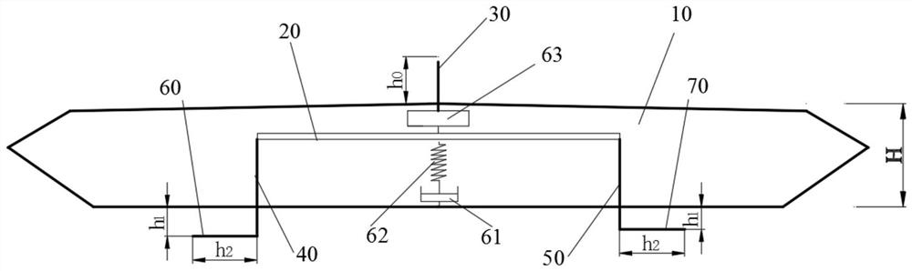
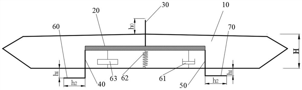
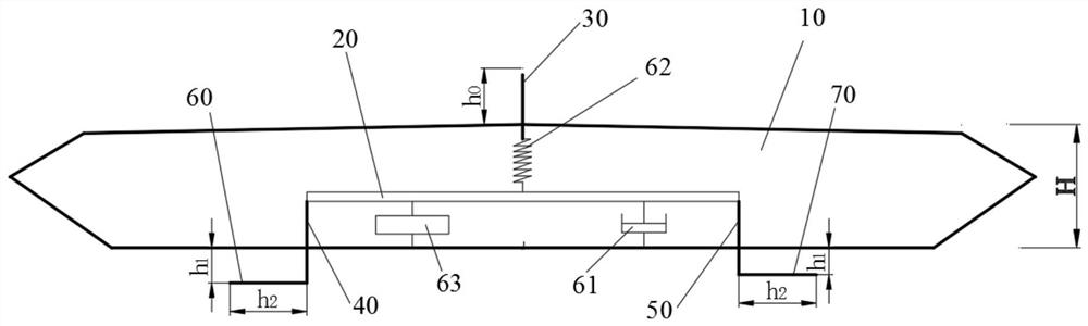
[0041] see also Figure 1-Figure 8C , the present invention provides some embodiments of a bridge movable aerodynamic measure device based on inertial capacity vibration reduction and a control method thereof. Of course, the movable aerodynamic measure device for bridges based on inertial capacity vibration reduction of the present invention can be used not only in main beams, but also in bridge towers and stay cables to reduce the vortex vibration of bridge towers and the wind-rain-induced vibration of stay cables. .

[0042] like figure 1As shown, a bridge movable aerodynamic...


PUM


Abstract

The invention discloses a bridge movable pneumatic measure device based on inertia capacity vibration reduction and a control method thereof. The bridge movable pneumatic measure device based on inertia capacity vibration reduction comprises an inertia capacity vibration damping system arranged at the bottom of the inner side of a box girder of a bridge, and a horizontal partition plate, a first vertical plate, a second vertical plate, a third vertical plate, a first horizontal plate and a second horizontal plate connected with the inertia capacity vibration damping system, wherein each vertical plate forms a vertical stable plate with adjustable height, and each horizontal plate forms two horizontal guide plates with adjustable length. When the bridge vibrates under the action of high wind speed, the horizontal partition plate on the inner side of the box girder can generate relative vibration, the vertical stable plate can extend out of the box girder, and the flow field of air around the cross section of the box girder can be changed so as to improve the critical wind speed of vibration; and when the bridge is subjected to low wind speed to generate vortex vibration, the horizontal guide plates can change the size and distribution of the vortex on the lower surface of the box girder so as to reduce the vortex vibration amplitude. According to the bridge movable pneumatic measure device based on inertia capacity vibration reduction, by means of the inertia capacity vibration damping system, the vibration energy of the box girder is accelerated and dissipated, the vibration amplitude of the bridge is reduced and the overall wind resistance of the bridge is improved.

Description

technical field [0001] The invention relates to the field of bridges, in particular to a bridge movable pneumatic measure device based on inertial capacity vibration reduction and a control method thereof. Background technique [0002] With the continuous growth of the span, high-performance steel has become the main material for the construction of long-span bridges, and steel box girder has been used in long-span cable-supported bridges due to its streamlined shape, small self-weight, and low cost under the same bearing capacity. Wide range of applications, such as the Nizhou Waterway Suspension Bridge of the Second Humen Bridge with a main span of 1688 meters and the cable-stayed bridge of the Sutong Yangtze River Bridge with a main span of 1088 meters. Although closed steel box girder has good aerodynamic performance, based on the current research results, the span limit of closed steel box girder bridge in terms of aerodynamic stability performance (mainly flutter perfo...

Claims


Application Information

Patent Timeline
Patent Type & Authority Patents(China)
IPC IPC(8): E01D19/00E01D2/04
CPCE01D2/04E01D19/00
Inventor 周锐周海俊严磊杜彦良
Owner SHENZHEN UNIV
Why Eureka
Try Eureka