Combustion chamber

A combustion chamber and fuel technology, applied in the field of aero-engines, can solve the problems of inability to meet the low pollution requirements of the engine, high CO and UHC emissions, uneven local equivalence ratio, etc., and achieve strong shearing, uniform combustion, and uniform mixing of oil and gas Effect

Active Publication Date: 2020-01-07
AECC COMML AIRCRAFT ENGINE CO LTD
View PDF10 Cites 4 Cited by
  • Summary
  • Abstract
  • Description
  • Claims
  • Application Information

AI Technical Summary

Problems solved by technology

In the small state, the equivalence ratio of the combustion zone is very low, far below the equivalence ratio range required for low-pollution combustion. At this time, although NOx emissions are low, CO and UHC emissions are high
In addition, because the conventional combustion chamber generally adopts the diffusion combustion method, the local equivalence ratio is not uniform, so for the conventional combustion chamber, it cannot meet the low pollution requirements in the entire engine operating range

Method used


Image

  • Combustion chamber
  • Combustion chamber
  • Combustion chamber

Examples


Embodiment Construction

[0029] Embodiments of the present invention will now be described in detail with reference to the accompanying drawings.

[0030] The present invention will be further described below in conjunction with the accompanying drawings and specific embodiments.

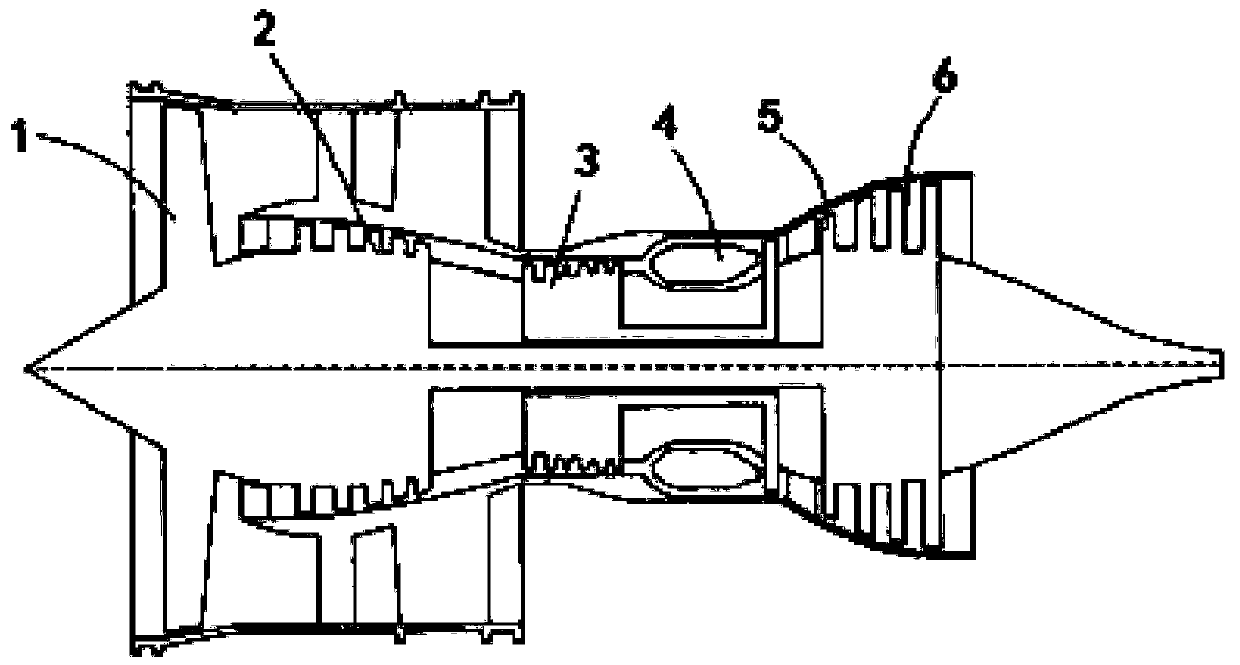
[0031] figure 1 Shown is the basic structure of an aeroengine applied to the combustor 4 , which includes a fan 1 , a low-pressure compressor 2 , a high-pressure compressor 3 , a combustor 4 , a high-pressure turbine 5 and a low-pressure turbine 6 . When the aero-engine is working, the incoming air flows through the fan 1, and after being compressed by the low-pressure compressor 2, it enters the high-pressure compressor 3, and then the high-pressure air enters the combustion chamber 4 to burn with fuel, and the high-temperature and high-pressure gas formed after combustion enters the The high-pressure turbine 5 and the low-pressure turbine 6 respectively drive the high-pressure compressor 3 , the fan 1 and the low-pressur...


PUM


Abstract

The invention aims to provide a combustion chamber. The combustion chamber adopts a single-ring-cavity flame tube structure, and the pollution emission of a whole LTO cycle of an engine is reduced onthe premise of ensuring the performance of the combustion chamber. In the combustion chamber, the main combustion stage involves an inner swirler, an outer swirler, an oil collecting ring and a premixing pre-evaporation section; the outer swirler adopts a radial swirler, the inner swirler adopts an axial swirler, and the oil collecting ring adopts direct fuel injection holes which are uniformly distributed in the circumferential direction, the fuel oil forms a direct spraying oil mist and forms the main combustion stage pneumatic atomizing oil mist by crushing and atomizing under the shearingaction of an inner swirling flow and an outer swirling flow; and the premixing pre-evaporation section adopts a nozzle structure and has a throat, the direct fuel injection holes are located in the 20%-80% range of the throat height relative to the radial position of the premixing pre-evaporation section of the main combustion stage, and the included angle between the injection direction of the direct fuel injection holes and the axis direction of the main combustion stage is negative 15 degrees to 60 degrees.

Description

technical field [0001] The invention relates to a combustion chamber structure, especially for an aero-engine. Background technique [0002] The basic performance and structural distribution of modern aero-engine combustors have reached a fairly high level, but there are still a lot of problems and challenges for modern aero-engine combustors. The development and application of new materials, new processes, new structures, and new concepts It is the source to ensure its continuous progress. [0003] The main development trend of modern civil aeroengine combustors is low-pollution combustion. Combustion chambers of civil aeroengines must meet increasingly stringent aeroengine pollution emission standards. The currently adopted CAEP6 (Committee on Aviation Environmental Protection) standard has very strict regulations on pollutant emissions, especially for NOx pollution emission requirements; and the latest CAEP8 standard proposes to reduce NOx emissions by 15% on the CAEP6 ...

Claims


Application Information

Patent Timeline
Patent Type & Authority Applications(China)
IPC IPC(8): F23R3/58
CPCF23R3/58
Inventor 徐榕何沛陈伟党龙飞鄂亚佳陈盼陈浩苏明明
Owner AECC COMML AIRCRAFT ENGINE CO LTD
Why Eureka
Try Eureka