Stent conveying device and stent loading method

A technology of a delivery device and an inner catheter, applied in the field of medical devices, can solve the problems of poor loading uniformity, poor loading uniformity of stents, etc.

Pending Publication Date: 2020-07-07
SHANGHAI MICROPORT CARDIOFLOW MEDTECH CO LTD
View PDF0 Cites 0 Cited by
  • Summary
  • Abstract
  • Description
  • Claims
  • Application Information

AI Technical Summary

Problems solved by technology

[0004] The object of the present invention is to provide a bracket delivery device and a bracket loading method, to solve the problem of low loading uniformity after the bracket is loaded into the existing bracket delivery device, and to use the existing bracket loading method to load the bracket easily to make the bracket The problem of low loading uniformity

Method used


Image

  • Stent conveying device and stent loading method
  • Stent conveying device and stent loading method
  • Stent conveying device and stent loading method

Examples


Embodiment 1

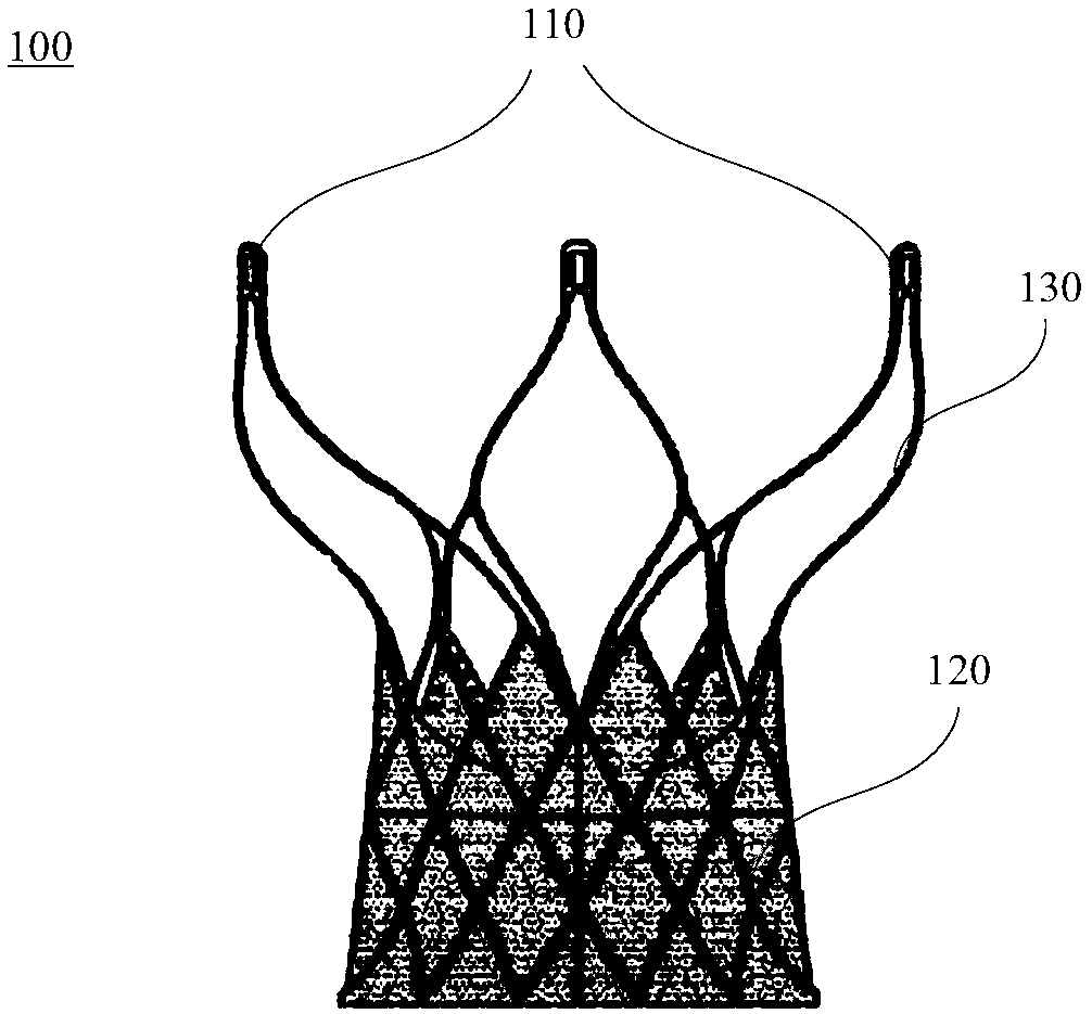
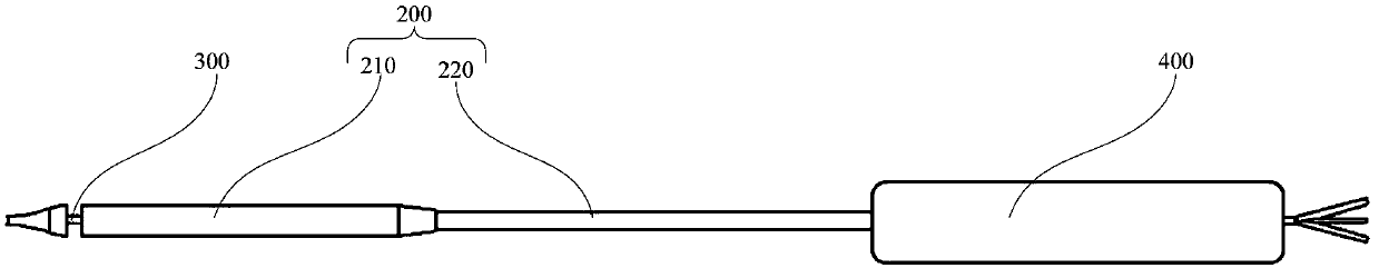
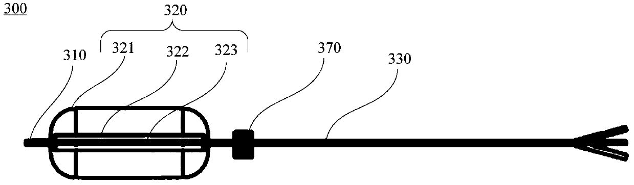
[0063] This embodiment provides a stent delivery device. figure 2 is a schematic structural view of the stent delivery device in Embodiment 1 of the present invention, image 3 It is a structural schematic view of the expanded inner catheter 300 in the stent delivery device in Embodiment 1 of the present invention, Figure 4 It is a schematic cross-sectional view of the inner catheter in the folded state of the stent delivery device in Embodiment 1 of the present invention, Figure 5 yes Figure 4 The cross-sectional schematic diagram of the stent delivery device along the line A-A, Figure 6 It is a schematic cross-sectional view of the first middle expansion tube in the inner catheter in the stent delivery device in Example 1 of the present invention in an expanded state, refer to Figure 2 to Figure 6 , the stent delivery device includes an outer tube assembly 200, an inner catheter 300, a handle 400, a medium delivery device, a first outer valve 510, a middle valve 520...

Embodiment 2

[0109] This embodiment provides a stent delivery device different from the stent delivery device in the first embodiment. refer to Figure 15 to Figure 17 , Figure 15 is a schematic cross-sectional view of the stent delivery device in the second embodiment of the present invention in a contracted state, Figure 16 yes Figure 15 The schematic cross-sectional view of the stent delivery device along the line B-B in , Figure 17 It is a schematic cross-sectional view of the stent delivery device in Example 2 of the present invention in the first expanded state. The difference between the stent delivery device in this example and the stent delivery device in Example 1 is that in this example, the The support catheter 710 and the connecting catheter 720 in the delivery device are different from the support catheter 320 and the connecting catheter 330 in the stent delivery device in the first embodiment.

[0110] refer to Figure 15 to Figure 17 , the stent delivery device inc...


PUM


Abstract

The invention provides a stent conveying device which comprises a sheath tube and an inner catheter, wherein the sheath tube is arranged outside the inner catheter in a sleeving manner; the inner catheter has a first expansion state; at the first expansion state, a stent is pressed and held in the sheath tube; the inner catheter is at a ball state; the outer surface of the inner catheter is adhered to the inner wall of the stent at the pressed and held state; and the outer diameter of the inner catheter is smaller than the inner diameter of the sheath tube. By adopting the stent conveying device, the stent is expanded through the inner catheter, so that the state of the stent pressed and held in the sheath tube can be adjusted, the phenomenon that the stent pressed and held in the sheath tube has non-uniform stress can be reduced, the loading uniformity of the stent can be improved, and furthermore, the risks that the release quality is affected, peripheral tissue is damaged, valve fatigue can be affected, even conveying systems are damaged and a retracement function is affected as twisting and sinking are caused in the release process because of the phenomena of the stent can be reduced, that is, the stent release success rate can be increased.

Description

technical field [0001] The invention relates to the technical field of medical devices, in particular to a stent delivery device and a stent loading method. Background technique [0002] With the development of social economy and the aging of the population, the incidence of valvular heart disease has increased significantly. Studies have shown that the incidence of valvular heart disease in the elderly population over 75 years old is as high as 13.3%. At present, traditional surgical treatment is still the first choice for patients with severe valvular disease, but for patients who are elderly, complicated with multiple organ diseases, have a history of thoracotomy, and have poor heart function, the risk of traditional surgery is high and death The rate is high, and some patients do not even have the chance of surgery. Transcatheter heart valve replacement has the advantages of no need for thoracotomy, less trauma, and faster recovery of patients, and has attracted extensi...

Claims


Application Information

Patent Timeline
IPC IPC(8): A61F2/958A61F2/966A61F2/97
CPCA61F2/958A61F2/966A61F2/97A61F2002/9583A61F2/95
Inventor 吴旭闻桂宝珠梅杰陈国明李雨
Owner SHANGHAI MICROPORT CARDIOFLOW MEDTECH CO LTD
Why Eureka
Try Eureka