
Key structure

a key cap and key technology, applied in the field of key cap structure, can solve the problems of limited thickness reduction, uneven stress on the flexible key cap, and key cap development by manufacturers

Active Publication Date: 2019-01-01
PRIMAX ELECTRONICS LTD
View PDF2 Cites 0 Cited by
  • Summary
  • Abstract
  • Description
  • Claims
  • Application Information

AI Technical Summary

Benefits of technology

The present invention provides a key structure that has a thin and light appearance and can prevent maloperation. It alleviates the problem of uneven stress on the flexible key cap by utilizing its structure and a conducting plate. An oblique pyramid is designed on the inner sidewall of the flexible key cap, which faces upwards with an asymmetrical slope. Extended protrusions on the conducting plate make contact with the oblique pyramids. This design ensures that any pressing force can be symmetrically distributed to the corner of the flexible key cap, preventing unauthorized pressing.

Problems solved by technology

However, the key structures developed by the manufacturers are still limited by the structure of the connecting element such as the scissor-type connecting element that connects the key cap and the baseboard, and the reduction in thickness is limited.
However, a new problem appears without configuring a scissor-type connecting element: uneven stress is apt to occur to the flexible key cap.
For example, when a user presses a corner of the flexible key cap, a pressing force applied to the flexible key cap by the user cannot be conducted from the corner to the whole flexible key cap because the flexible key cap is made of a flexible elastic rubber material and the support force of the flexible key cap is not sufficient without configuring a scissor-type connecting element.
That is, uneven stress of the flexible key cap is apt to occur when the user presses, and therefore it is impossible to generate a key signal, resulting in maloperation.

Method used


Image

  • Key structure
  • Key structure
  • Key structure

Examples


Embodiment Construction

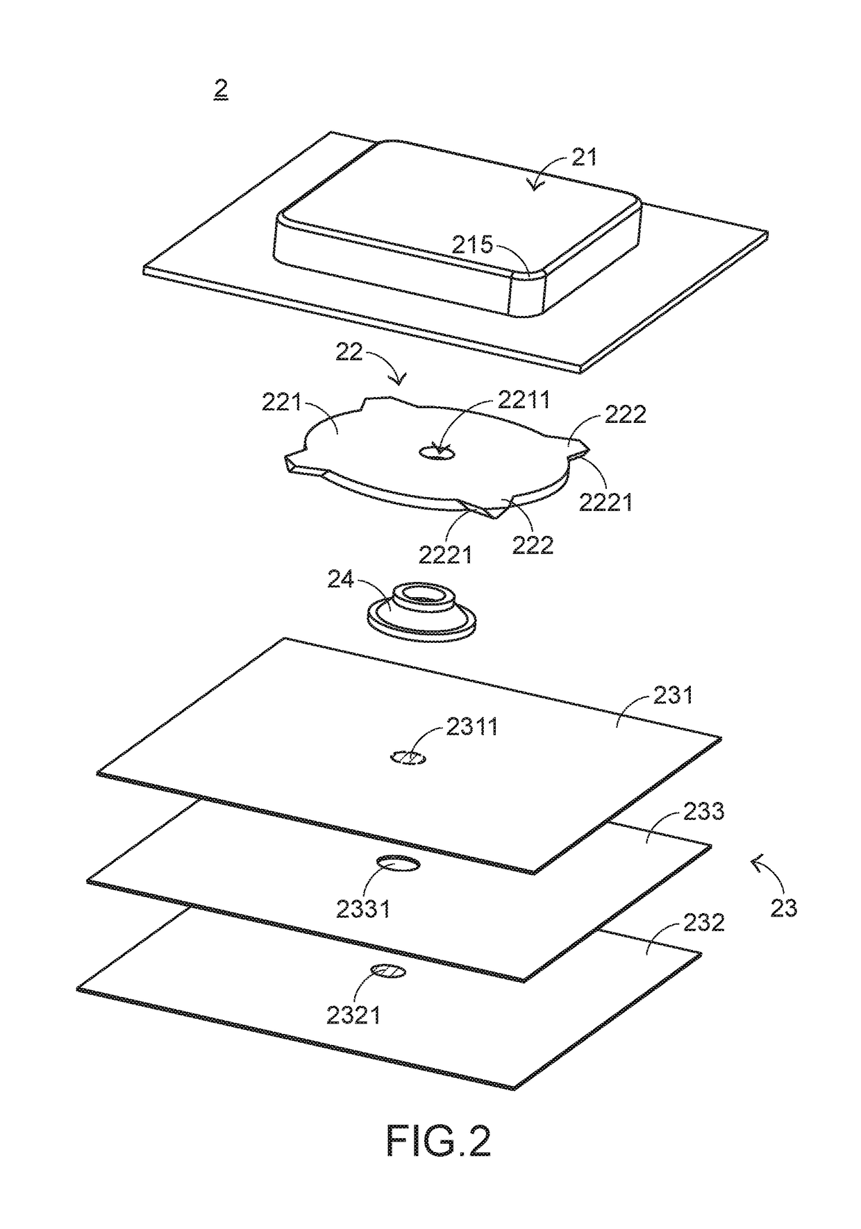
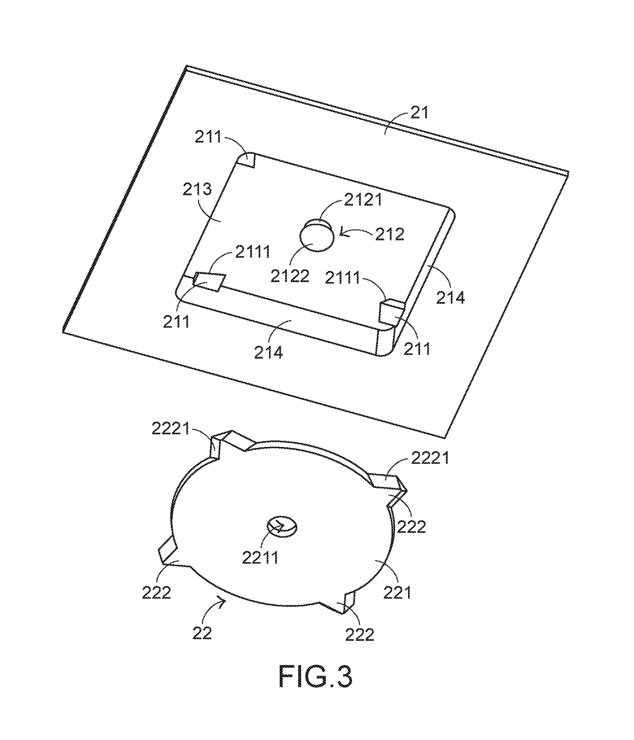
[0019]In view of the problem of the existing technology, the present invention provides a key structure having a thin and light appearance and capable of avoiding maloperation, so as to resolve the problem of the existing technology. Referring to FIG. 2 and FIG. 3, FIG. 2 is a schematic structural exploded diagram of a key structure according to a preferable embodiment of the present invention, and FIG. 3 is a schematic structural diagram of a flexible key cap and a conducting plate of a key structure of the present invention according to a preferable embodiment of the present invention. The key structure 2 includes a flexible key cap 21, a conducting plate 22, a switch circuit board 23, and an elastic element 24. The flexible key cap 21 is exposed out of the key structure 2 and is capable of being pressed to deform, and the flexible key cap 21 includes a plurality of oblique pyramids 211 and a fixing column 212. The conducting plate 22 is fixed on an inner surface 213 of the flexib...


PUM


Abstract

The present invention relates to a key structure, including a flexible key cap, a conducting plate, a switch circuit board capable of generating a key signal, and an elastic element. The conducting plate is fixed on an inner surface of the flexible key cap and in contact with a plurality of inner sidewalls of the flexible key cap. The switch circuit board is disposed below the conducting plate, and the elastic element is disposed between the conducting plate and the switch circuit board. When the flexible key cap receives the pressing force, the conducting plate twists due to deformation of the flexible key cap, and pushes the plurality of inner sidewalls of the flexible key cap, so as to conduct a pressing force to a corner of the flexible key cap.

Description

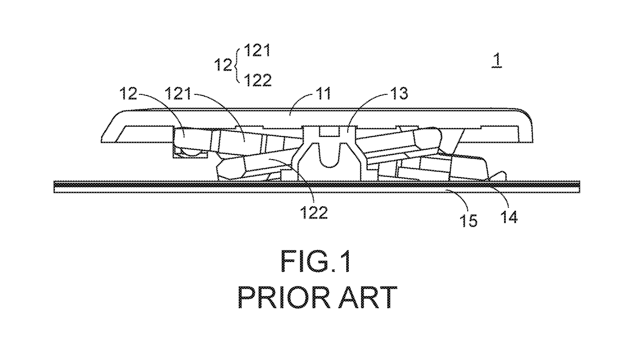
FIELD OF THE INVENTION[0001]The present invention relates to a key structure, and in particular, to a key structure having a thin and light appearance.BACKGROUND OF THE INVENTION[0002]Common peripheral input devices of a computer include a mouse, a keyboard device, a trackball device, and the like. The keyboard can be used by users to directly input words and symbols to the computer and is therefore draw attention from users and input device manufacturers. A keyboard including a scissor-type connecting element is pretty common.[0003]Subsequently, the architecture of a key structure in a keyboard having a scissor-type connecting element is described. Referring to FIG. 1, FIG. 1 is a schematic cross-sectional side view of a conventional key structure. A conventional key structure 1 includes a key cap 11, a scissor-type connecting element 12, an elastic rubber body 13, a membrane switch circuit 14, and a baseboard 15, and the baseboard 15 is configured to bear the key cap 11, the sciss...

Claims


Application Information

Patent Timeline
Patent Type & Authority Patents(United States)
IPC IPC(8): H01H13/705H01H13/14H01H13/704H01H3/12
CPCH01H13/705H01H13/14H01H13/704H01H3/12H01H13/7065H01H2215/006H01H2221/024H01H2221/058H01H2227/036
Inventor TSAI, LEI-LUNG
Owner PRIMAX ELECTRONICS LTD
Learn More