
Rim sealing structure comprising wave-shaped hollows and turbine using rim sealing structure

A technology of sealing structure and concave structure, which is applied in the field of turbines, can solve the problems of limited effect and achieve the effects of convenient processing, increased circumferential uniformity, and enhanced fluid mixing

Inactive Publication Date: 2018-11-13
HARBIN ENG UNIV
View PDF5 Cites 0 Cited by
  • Summary
  • Abstract
  • Description
  • Claims
  • Application Information

AI Technical Summary

Problems solved by technology

Although the existing axial and radial flange sealing structures can reduce the degree of gas intrusion to a certain extent, the effect is limited, especially under variable working conditions

Method used


Image

  • Rim sealing structure comprising wave-shaped hollows and turbine using rim sealing structure
  • Rim sealing structure comprising wave-shaped hollows and turbine using rim sealing structure
  • Rim sealing structure comprising wave-shaped hollows and turbine using rim sealing structure

Examples


Embodiment Construction

[0016] The present invention will be further described in detail below in conjunction with the accompanying drawings and specific embodiments.

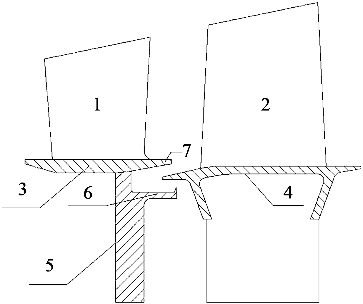
[0017] to combine Figure 1~4 , the present invention is made up of hub (comprising stationary blade hub flange 3 and moving blade hub flange 4), stationary blade 1, moving blade 2 and casing (not shown in the figure), between the hub and the casing along the circumference Install the stationary blade 1 and the moving blade 2 evenly in the direction, the stationary blade 1 is in the front, and the moving blade 2 is behind. On the rotor hub flange plate 4 and connected with the rotor blade rotating disc, a cold flow channel is formed between the stationary blade partition plate 5 and the rotor blade rotating disc, and is set at the edge of the partition plate below the rear side of the stator hub flange plate 3 The sealing teeth 6 on the side of the stator blade, the tops of the sealing teeth protrude radially upwards in a sickle shap...


PUM


Abstract

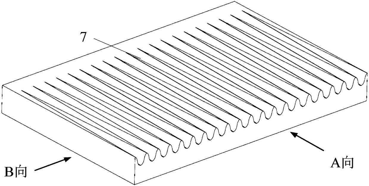
The invention provides a rim sealing structure comprising wave-shaped hollows and a turbine using the rim sealing structure. A stationary blade is installed on a stationary blade hub margin plate; a movable blade is installed on a movable blade hub margin plate; the edge of a partition plate below the rear side of the stationary blade hub margin plate is provided with stationary blade side sealingteeth; the top ends of the sealing teeth protrude upwards in the radial direction to form a sickle shape; a wave-shaped hollow structure is arranged at the rear side of the stationary blade hub margin plate; hollows are toward an air outlet angle of the stationary blade; the depth of the hollows is gradually increased along the flow direction; the front side of the movable blade hub margin plateis inserted between the stationary blade hub margin plate and the stationary blade side sealing teeth in a staggered manner so as to form the rim sealing structure which is provided with the wave-shaped hollows. The rim sealing structure provided by the invention has the advantages of improving the circumferential uniformity of air flow at the position, close to the end wall of a rim, of the outlet of the stationary blade, reducing the requirements of the rotary disc of the movable blade on the minimum cooling and sealing flow, also straightening the air flow, close to the end wall of the rim,of the outlet of the stationary blade, reducing the probability of invasion of gas under full conditions, and improving the aerodynamic efficiency of the turbine.

Description

technical field [0001] The invention relates to a turbine structure, in particular to a wheel rim sealing structure with a wave-like depression and a turbine using the structure. Background technique [0002] In gas turbine / aeroengine turbine components, due to the pumping effect of the turbine disc rotation, the cold air in the disc cavity will be continuously pumped out, resulting in a decrease in the airflow pressure in the sealing cavity, so under the action of the pumping effect, when the pump When the outflow flow is greater than the cold air supply flow, gas intrusion will occur at the rim of the turbine disk, that is, the mainstream gas enters the static chamber of the turbine disk cavity structure through the rim sealing structure. In addition, the mutual interference between the rotating vanes in the main flow channel will cause the circumferential pressure fluctuation of the main flow gas, which will also cause gas intrusion. Gas intrusion will destroy the coolin...

Claims


Application Information

Patent Timeline
Patent Type & Authority Applications(China)
IPC IPC(8): F01D11/00F01D11/04
Inventor 高杰褚召丰原泽姜玉廷郑群
Owner HARBIN ENG UNIV
Learn More