
A spring bar fatigue test device and monitoring system

A fatigue test and monitoring system technology, applied in measuring devices, using repetitive force/pulsation force to test the strength of materials, instruments, etc., can solve problems such as low test accuracy and clip displacement

Active Publication Date: 2020-08-11
成都西交轨道交通技术服务有限公司
View PDF10 Cites 0 Cited by
  • Summary
  • Abstract
  • Description
  • Claims
  • Application Information

AI Technical Summary

Problems solved by technology

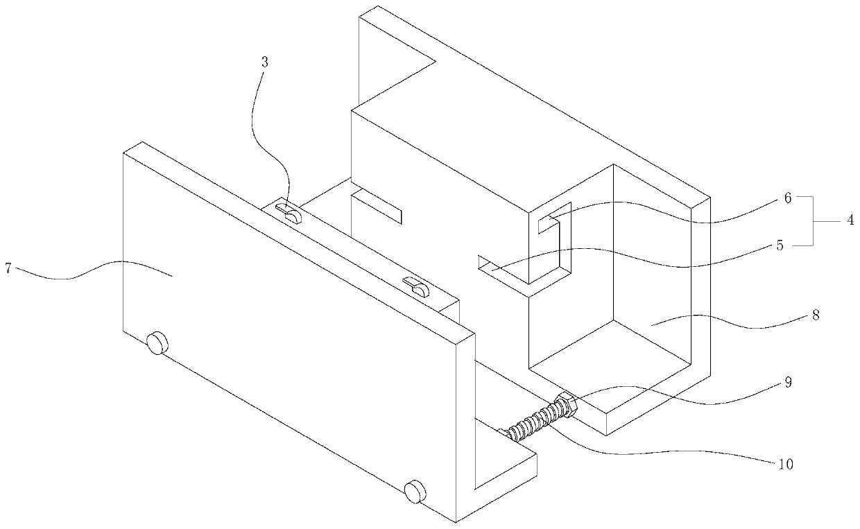
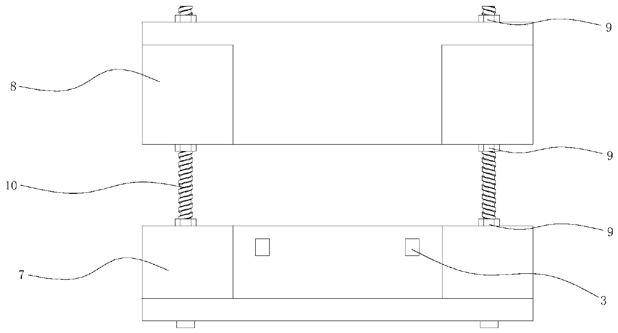
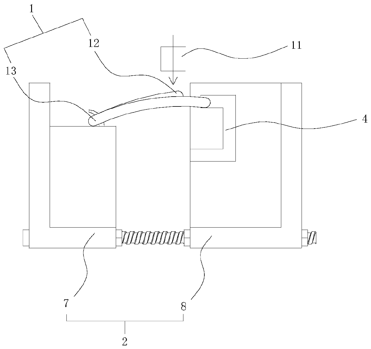
[0003] In the existing elastic strip fatigue test device, it is actually impossible to keep the elastic strip in a stable position, so that when the pressure is applied, the elastic strip is displaced, resulting in low test accuracy

Method used


Image

  • A spring bar fatigue test device and monitoring system
  • A spring bar fatigue test device and monitoring system
  • A spring bar fatigue test device and monitoring system

Examples


Embodiment Construction

[0031] In order to make the purpose, technical solutions and advantages of the embodiments of the present invention clearer, the technical solutions in the embodiments of the present invention will be clearly and completely described below in conjunction with the drawings in the embodiments of the present invention. Obviously, the described embodiments It is a part of embodiments of the present invention, but not all embodiments. The components of the embodiments of the invention generally described and illustrated in the figures herein may be arranged and designed in a variety of different configurations.

[0032] Accordingly, the following detailed description of the embodiments of the invention provided in the accompanying drawings is not intended to limit the scope of the claimed invention, but merely represents selected embodiments of the invention. Based on the embodiments of the present invention, all other embodiments obtained by persons of ordinary skill in the art wi...


PUM


Abstract

The invention belongs to the technical field of railway accessories, and discloses an elastic strip fatigue test device. The test device comprises an elastic strip and an installation body, wherein lugs extending towards a direction far away from the installation body are arranged at one end of the installation body, and rail grooves for embedding the elastic strip are formed at the other end; a pair of lugs and a pair of rail grooves are provided; each lug is an arc structure, and a lower end of each rail groove is an inlet end, and an upper end thereof is a closed end for limiting. Through the test device disclosed by the invention, the elastic strip can be stably installed on the test device, the test precision is ensured, and the vibration condition of the actual working condition canbe well simulated. The invention further discloses a monitoring system for well detecting the test device, thereby guaranteeing the smooth operation of the test process.

Description

technical field [0001] The invention belongs to the technical field of railway accessories, in particular to a spring bar fatigue test device and a monitoring system. Background technique [0002] The railway uses the rail fastener clip system as part of the lower foundation of the railway; the clip can press the rail through its own elastic buckle, provide a certain rigidity and damping for the rail, and provide sufficient buckle pressure. In order to ensure the performance of the clips, all major manufacturers will test the clips, and use the method of sampling inspection to check the quality of the clips produced by fatigue. [0003] In the existing clip fatigue test device, it is actually impossible to keep the clip in a stable position, so when the pressure is applied, the clip is displaced, resulting in low test accuracy. Contents of the invention [0004] In order to solve the above problems, the present invention discloses a spring bar fatigue test device, which c...

Claims


Application Information

Patent Timeline
Patent Type & Authority Patents(China)
IPC IPC(8): G01N3/32G01N3/02
CPCG01N3/02G01N3/32G01N2203/0005G01N2203/0019G01N2203/0073G01N2203/0252G01N2203/0676G01N2203/0682
Inventor 孙钦秋任艳红杨晨邹栋陈勖
Owner 成都西交轨道交通技术服务有限公司
Learn More