
Storage system and IO disk falling method and device thereof

A storage system and storage technology, applied in the field of storage systems, can solve problems such as inconsistency in the upper limit of the rate, hysteresis, and the complexity of the merging process, and achieve the effect of simplifying the process of IO merging and reducing the lag

Active Publication Date: 2020-01-10
INSPUR SUZHOU INTELLIGENT TECH CO LTD
View PDF3 Cites 4 Cited by
  • Summary
  • Abstract
  • Description
  • Claims
  • Application Information

AI Technical Summary

Problems solved by technology

However, in the emerging all-flash products, a log-type storage method is adopted, so that multiple small IOs must be merged into a large IO through a complex process before they can be placed, that is, batch IO data; due to the time introduced by IO merging delay, so that the existing statistics of small IO response delay indicators cannot truly reflect the delay of data placement; and due to the complexity of the existing IO merging process, the scheme based on large IO statistics of placement time has a certain lag. As a result, the actual upper limit of the rate is inconsistent with the rate limit of the leaky bucket current limiting algorithm, especially in scenarios where the proportion of the used cache varies greatly, and it is difficult to accurately control IO placement

Method used


Image

  • Storage system and IO disk falling method and device thereof
  • Storage system and IO disk falling method and device thereof

Examples


Embodiment Construction

[0042] In order to make the purpose, technical solutions and advantages of the embodiments of the present invention clearer, the technical solutions in the embodiments of the present invention will be clearly and completely described below in conjunction with the drawings in the embodiments of the present invention. Obviously, the described embodiments It is a part of embodiments of the present invention, but not all embodiments. Based on the embodiments of the present invention, all other embodiments obtained by persons of ordinary skill in the art without making creative efforts belong to the protection scope of the present invention.

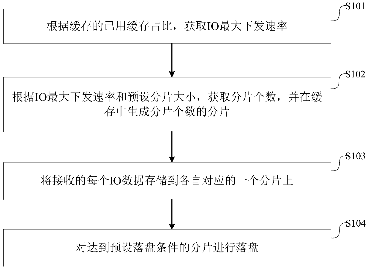
[0043] Please refer to figure 1 , figure 1 It is a flow chart of an IO flushing method of a storage system provided by an embodiment of the present invention. The method can include:

[0044] Step 101: Obtain the maximum IO sending rate according to the used cache ratio of the cache.

[0045] It can be understood that the purpose of this ...


PUM


Abstract

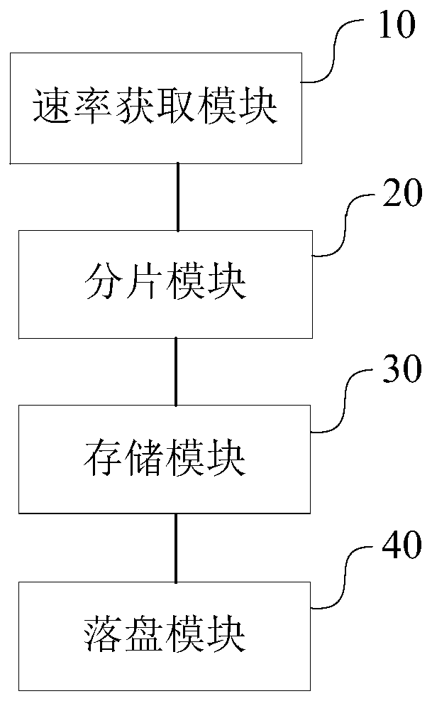
The invention discloses an IO disk falling method and device for a storage system and the storage system. The IO disk falling method comprises the steps: obtaining the maximum IO issuing rate according to the used cache proportion of a cache; obtaining the number of fragments according to the IO maximum issuing rate and a preset fragment size, and generating fragments with the number of fragmentsin a cache; storing each piece of received IO data to a respective corresponding fragment; and enabling the fragments meeting the preset disc falling condition to be subjected to disc falling. According to the IO disk falling method, IO data on each fragment form a large IO for disk falling; the IO merging process is simplified; and the delay of the drop time delay of the batch drop IO data is reduced, and the consistency of the upper limit of the actual rate and the upper limit of the rate of the leaky bucket current limiting algorithm is ensured on the basis of meeting the requirement of full flash storage of the batch drop IO data, so that the IO drop can be accurately controlled by subsequently utilizing the drop time delay and the dynamic regulation rate of the fragments.

Description

technical field [0001] The present invention relates to the technical field of storage systems, in particular to a storage system IO loading method, device and storage system. Background technique [0002] With the development of science and technology in modern society, the application of storage system is more and more extensive. At present, the dynamic balanced leaky bucket current limiting algorithm commonly used in traditional storage systems performs IO (Input / Output input / output, that is, read / write) storage, that is, to send IO data to the disk. The core idea is as follows: According to The proportion of the used cache determines the maximum rate of IO data delivery, and the response time of the lower layer is counted, and the rate is adjusted on the basis of the maximum rate to achieve a balance between data request and processing speed. However, in the emerging all-flash products, a log-type storage method is adopted, so that multiple small IOs must be merged into...

Claims


Application Information

Patent Timeline
Patent Type & Authority Applications(China)
IPC IPC(8): G06F3/06
CPCG06F3/061G06F3/0629G06F3/0656G06F3/0683
Inventor 刘志魁
Owner INSPUR SUZHOU INTELLIGENT TECH CO LTD
Learn More