Supercharge Your Innovation With Domain-Expert AI Agents!

A chip mounter

A chip mounting and equipment technology, applied in the direction of electrical components, electrical components, circuits, etc., can solve the problems of inability to meet the requirements of high-end packaging, low mounting accuracy of chip mounting equipment, etc., and achieve the effect of improving mounting accuracy

Active Publication Date: 2021-02-19
CHONGQING COLLEGE OF ELECTRONICS ENG
View PDF8 Cites 0 Cited by
  • Summary
  • Abstract
  • Description
  • Claims
  • Application Information

AI Technical Summary

Problems solved by technology

[0003] The purpose of the present invention is to provide a chip mounting equipment, which aims to solve the technical problem that the mounting accuracy of the chip mounting equipment in the prior art is low and cannot meet the requirements of high-end packaging

Method used


Image

  • A chip mounter
  • A chip mounter
  • A chip mounter

Examples


Embodiment Construction

[0020] Embodiments of the present invention are described in detail below, examples of which are shown in the drawings, wherein the same or similar reference numerals designate the same or similar elements or elements having the same or similar functions throughout. The embodiments described below by referring to the figures are exemplary and are intended to explain the present invention and should not be construed as limiting the present invention.

[0021] In describing the present invention, it should be understood that the terms "length", "width", "upper", "lower", "front", "rear", "left", "right", "vertical", The orientation or positional relationship indicated by "horizontal", "top", "bottom", "inner", "outer", etc. are based on the orientation or positional relationship shown in the drawings, and are only for the convenience of describing the present invention and simplifying the description, rather than Nothing indicating or implying that a referenced device or element...


PUM


Abstract

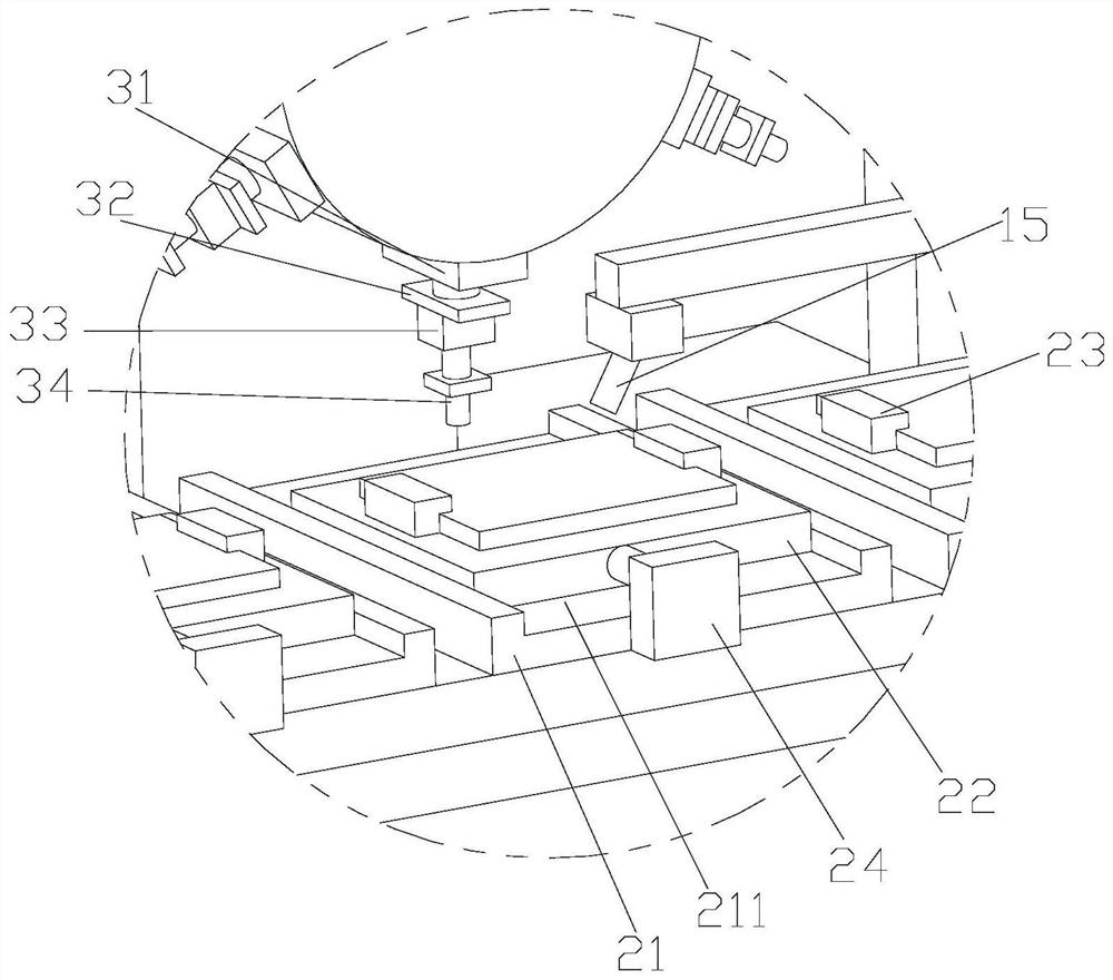
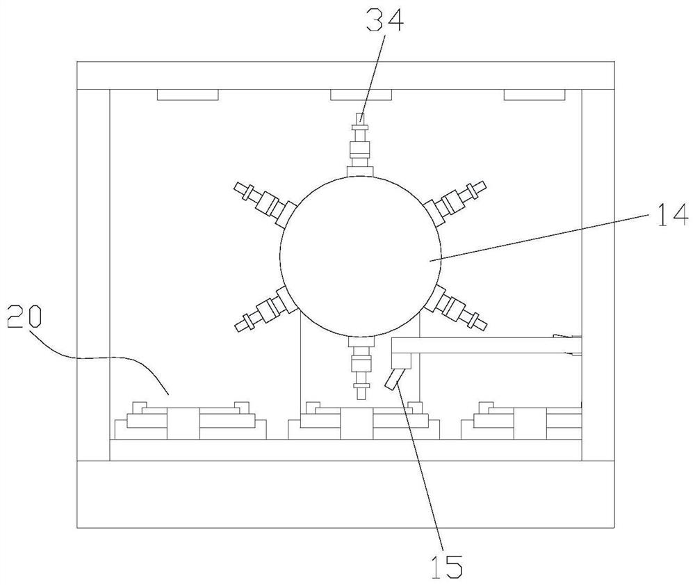
The invention discloses chip mounting equipment. A first conveying belt is arranged on the upper surface of a workbench. A supporting plate is fixedly connected with the first conveying belt. A sliding groove is formed in the supporting plate. A sliding block is connected with the supporting plate in a sliding mode. A locking piece is fixedly connected with the sliding block. A first pushing pieceis fixedly connected with the supporting plate. A support is fixedly connected with the workbench. The second conveying belt is arranged on the support. A chip is arranged on the second conveying belt. A rotary disc is arranged between the first conveying belt and the second conveying belt. An adsorption mounting assembly is fixedly connected with the rotary disc and located on the outer side wall of the rotary disc. A first camera is fixedly connected with the support and located above the first conveying belt; and a second camera is fixedly connected with the support and is close to the rotary disc. The chip mounting equipment reaches the purposes of improving the mounting precision and meeting the requirement of high-end packaging.

Description

technical field [0001] The invention relates to the field of packaging technology, in particular to a chip mounting device. Background technique [0002] Chip mounting is one of the key equipment in semiconductor packaging equipment. In recent years, with the widespread application of high-end packaging, higher requirements have been put forward for chip mounting accuracy, but the mounting accuracy of existing chip mounting equipment is low. Can not meet the requirements of high-end packaging. Contents of the invention [0003] The object of the present invention is to provide a chip mounting equipment, aiming to solve the technical problem that the chip mounting equipment in the prior art has low mounting accuracy and cannot meet the requirements of high-end packaging. [0004] In order to achieve the above object, a chip mounting equipment used in the present invention includes a workbench, a first conveyor belt, a moving assembly, a bracket, a second conveyor belt, a t...

Claims


Application Information

Patent Timeline
Patent Type & Authority Patents(China)
IPC IPC(8): H01L21/67
CPCH05K13/0409H05K13/081
Inventor 刘睿强李志贵周胜
Owner CHONGQING COLLEGE OF ELECTRONICS ENG
Features
  • R&D
  • Intellectual Property
  • Life Sciences
  • Materials
  • Tech Scout
  • Unparalleled Data Quality
  • Higher Quality Content
  • 60% Fewer Hallucinations
Learn More