Optical cable line fault location and visualization method and system based on AI image recognition

A line fault and optical cable technology, which is applied in the field of optical cable fault location and visualization methods and systems, can solve the problems that maintenance personnel cannot know the fault type and cause in advance, and the optical cable fault point location method cannot accurately locate, so as to reduce the troubleshooting time. , Improve maintenance efficiency and reduce losses

Active Publication Date: 2022-06-24
STATE GRID ZHEJIANG ELECTRIC POWER CO LTD JINHUA POWER SUPPLY CO +2
View PDF5 Cites 0 Cited by
  • Summary
  • Abstract
  • Description
  • Claims
  • Application Information

AI Technical Summary

Problems solved by technology

[0004] The present invention mainly solves the technical problems that the original optical cable fault location method cannot be accurately located and maintenance personnel cannot know the type and cause of the fault in advance; it provides an optical cable line fault location and visualization method and system based on AI image identification, which can not only accurately locate the optical cable The point of failure, maintenance personnel can also know the type and cause of the failure in advance

Method used


Image

  • Optical cable line fault location and visualization method and system based on AI image recognition
  • Optical cable line fault location and visualization method and system based on AI image recognition
  • Optical cable line fault location and visualization method and system based on AI image recognition

Examples


Embodiment

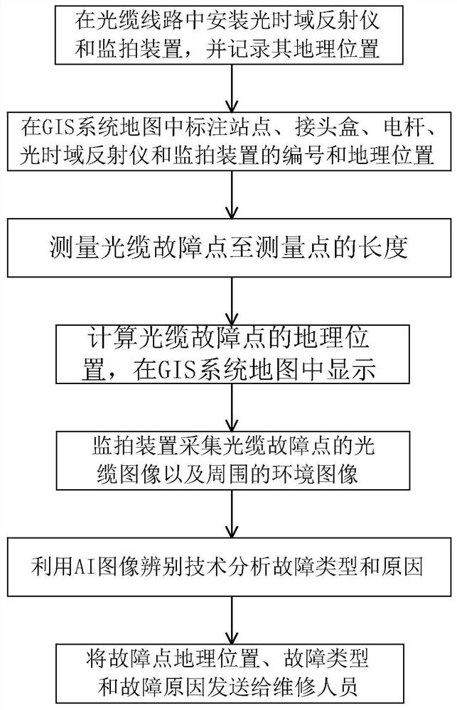
[0053] Embodiment: The fault location and visualization method of optical cable line based on AI image recognition in this embodiment, such as figure 1 shown, including the following steps:

[0054] Step 1): install an optical time domain reflectometer and a monitoring device in the optical cable line (the monitoring device is a camera, a camera, etc.), and record its geographic location;

[0055] Step 2): mark the number and geographic location of the site, joint box, pole, optical time domain reflectometer and monitoring device in the GIS system map, and bind and store the above number and geographic location in the GIS database;

[0056] Step 3): use an optical time domain reflectometer (OTDR) to measure the length from the fault point of the optical cable to the measurement point (the measurement point is the location of the optical time domain reflectometer) multiple times, and take the average value as the basis for subsequent calculations;

[0057] Step 4): Calculate t...


PUM


Abstract

The invention discloses an optical cable line fault location and visualization method and system based on AI image identification, wherein the method includes: installing an optical time domain reflectometer and a monitoring device in the optical cable line; visualizing the optical cable line in a GIS system map; measuring the optical cable The length from the fault point to the measurement point; calculate the geographical location of the fault point of the optical cable; the monitoring device collects the cable image of the fault point of the optical cable and the surrounding environment image and uploads it to the monitoring management platform; the monitoring management platform performs fault image recognition and fault analysis. The system includes optical time domain reflectometer, monitoring device and monitoring management platform. The invention solves the problem that the fault point of the optical cable cannot be accurately located in the prior art, and can accurately locate the fault point of the optical cable, and can clearly know the type and cause of the fault of the optical cable while locating, so that maintenance personnel can quickly arrive at the scene and facilitate maintenance personnel Prepare maintenance tools and plans in advance to improve maintenance efficiency and reduce losses.

Description

technical field [0001] The invention relates to the field of on-line monitoring of optical cable faults, in particular to a method and system for locating and visualizing optical cable line faults based on AI image identification. Background technique [0002] Optical cable lines extend vertically and horizontally for a long distance, in different environments, and many line poles and towers pass through the complex terrain, which brings great inconvenience to the daily work of operation and maintenance personnel. At the same time, in real life, the destruction of external natural disasters, man-made theft, and brutal construction such as construction vehicles and tall machinery are easy to cause damage to optical cable lines, resulting in interruption of power communication and even casualties. According to statistics, it takes several hours to repair an optical cable accident. If an optical fiber is interrupted for 1 hour, it will cost 500,000 to 600,000 yuan. The economic...

Claims


Application Information

Patent Timeline
Patent Type & Authority Patents(China)
IPC IPC(8): H04B10/071H04N7/18G06F16/29G06V20/52
CPCH04B10/071H04N7/188G06F16/29G06V20/52
Inventor 厉立锋倪旭明王斌邵航军赵凯美赵翔郭瑜张晖黄兰英
Owner STATE GRID ZHEJIANG ELECTRIC POWER CO LTD JINHUA POWER SUPPLY CO
Why Eureka
Try Eureka