Supercharge Your Innovation With Domain-Expert AI Agents!

Light guide unit, display device and optical detection device

A technology of optical detection and light guide unit, which is applied in optics, nonlinear optics, instruments, etc., can solve the problem of low transmittance of imaging beam, achieve good user experience, avoid transmission loss, and achieve good biometric detection effect under the screen Effect

Inactive Publication Date: 2020-01-24
LIUZHOU FUMIN TECH CO LTD
View PDF0 Cites 4 Cited by
  • Summary
  • Abstract
  • Description
  • Claims
  • Application Information

AI Technical Summary

Problems solved by technology

However, for non-self-luminous display screens, such as liquid crystal display screens, which usually include a display panel and a backlight module, the transmittance of the imaging beam required for under-screen biometric detection is low

Method used


Image

  • Light guide unit, display device and optical detection device
  • Light guide unit, display device and optical detection device
  • Light guide unit, display device and optical detection device

Examples


Embodiment Construction

[0026] In the detailed description of the embodiments of the present invention, it should be understood that when a substrate, frame, sheet, layer or pattern is referred to as being "on" or "under" another substrate, another sheet, another layer or another pattern , it may be "directly" or "indirectly" on another substrate, another sheet, another layer or another pattern, or one or more intermediate layers may also be present. For the purpose of clarity, the thickness and size of each layer in the drawings of the specification may be exaggerated, omitted, or schematically represented. Also, the size of elements in the drawings does not utterly reflect an actual size.

[0027] The following will clearly and completely describe the technical solutions in the embodiments of the present invention with reference to the accompanying drawings in the embodiments of the present invention. Obviously, the described embodiments are only some, not all, embodiments of the present invention....


PUM


Abstract

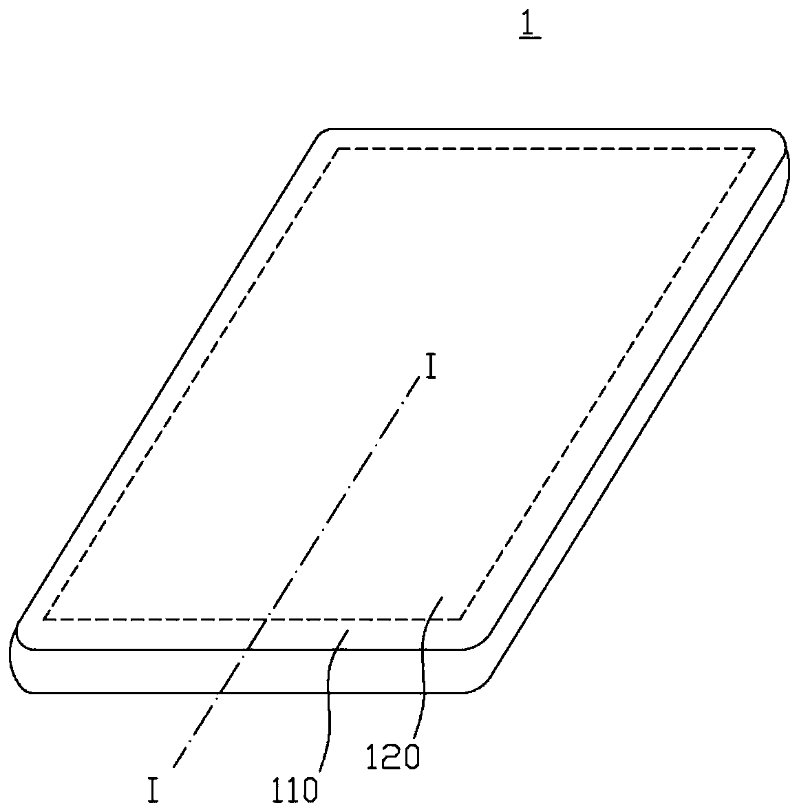
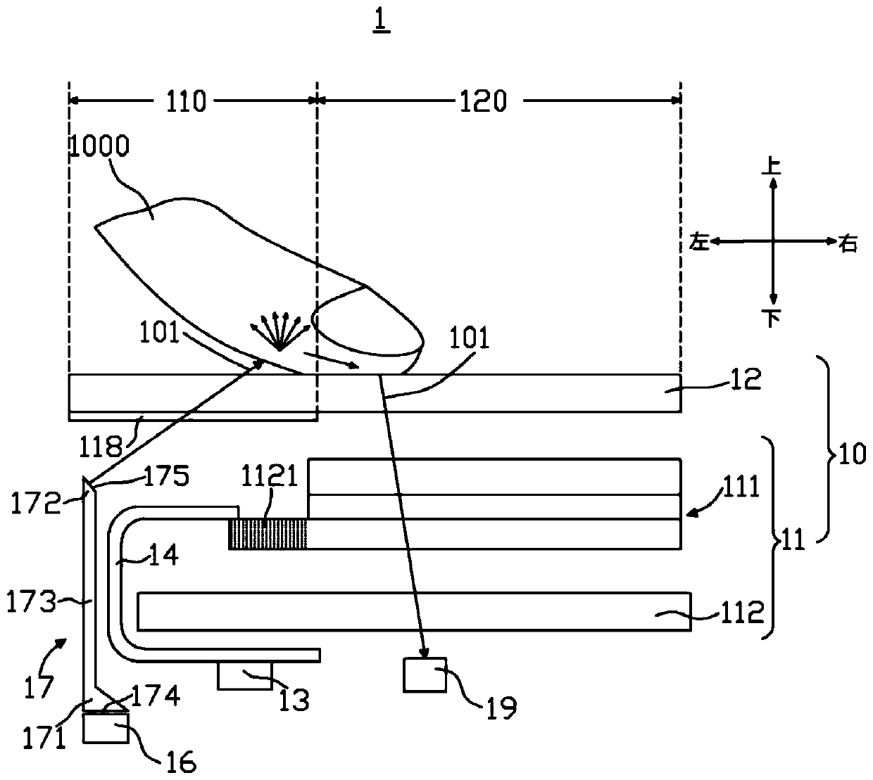
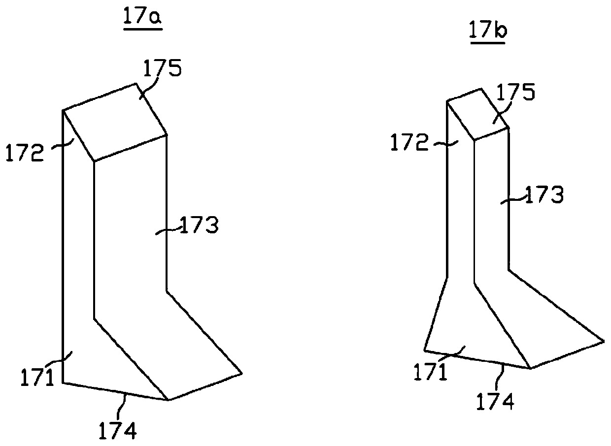
The invention discloses an optical detection device. The optical detection device comprises a protective layer, a display screen, a light guide unit and a light source, wherein the display screen is located below the protective layer and comprises a display panel and a backlight module, the display panel comprises a flexible circuit board, and the flexible circuit board is partially connected witha terminal, is bent outwards and extends to a position below the backlight module; the output end of the light guide unit is located below a non-transparent region, and the input end of the light guide unit is away from the non-transparent region compared with the output end; the light source is used for transmitting a detection beam to the input end of the light guide unit, the detection beam enters the light guide unit from the input end and is transmitted from the output end, and the detection beam transmitted from the output end can penetrate out of the protective layer from the non-transparent region to be projected on an external object located above the protective layer; and the flexible circuit board is provided with an opening, the opening is right opposite to at least one part of the terminal, and at least one part of the light guide unit is arranged in the opening of the flexible circuit board. The optical detection device has a good under-screen biological characteristic detection effect.

Description

technical field [0001] The invention relates to the field of optoelectronic technology, in particular to a light guide unit, a display device and an optical detection device. Background technique [0002] With the advancement of technology and the improvement of people's living standards, users require more functions and stylish appearances for electronic products such as mobile phones, tablet computers, and cameras. At present, the development trend of mobile phones is to have a higher screen-to-body ratio and have functions such as front camera Selfie and face recognition. As the functions supported by the optical detection device become more and more abundant, the number of components that need to be installed is also increasing, and it needs to occupy a part of the display area on the front of the optical detection device, which affects the appearance and user experience. [0003] Recently, in order to achieve full-screen or near-full-screen effects, off-screen biometri...

Claims


Application Information

Patent Timeline
IPC IPC(8): G02F1/1333G02F1/1335G06K9/00G06K9/20
CPCG02F1/13338G02F1/1335G06V40/1341G06V40/13G06V10/147
Inventor 朱文龙周扬
Owner LIUZHOU FUMIN TECH CO LTD
Features
  • R&D
  • Intellectual Property
  • Life Sciences
  • Materials
  • Tech Scout
  • Unparalleled Data Quality
  • Higher Quality Content
  • 60% Fewer Hallucinations
Learn More