High-frequency module

a high-frequency module and module technology, applied in the direction of transmission, electrical equipment, etc., can solve the problem of difficulty in reducing the size of the high-frequency module, and achieve the effect of reducing the siz

Active Publication Date: 2013-06-18
MURATA MFG CO LTD
View PDF7 Cites 5 Cited by
  • Summary
  • Abstract
  • Description
  • Claims
  • Application Information

AI Technical Summary

Benefits of technology

[0011]With this configuration, the antenna filter attenuates third and higher harmonic frequency bands. This makes it possible to simplify the configuration of the antenna filter and to prevent transmission loss between the switch IC and the antenna through which, not only transmission signals, but also reception signals pass. That is, a high-frequency module is provided which has a smaller size and a reduced transmission loss as compared to a high-frequency module in which an individual-terminal filter is provided for each of transmission signals. Further, by providing an individual-terminal filter for the individual terminals to attenuate at least second harmonic frequencies, a second harmonic having a relatively high magnitude is prevented from being input into the switch IC.
[0013]With this configuration, some of the higher harmonics of all of the transmission signals input into the individual terminals of the switch IC can be attenuated in the antenna filter. This makes it possible to omit some of the components of the individual-terminal filter, so as to further reduce the size of the high-frequency module.
[0016]With this configuration, the antenna filter functions, not only as a low-pass filter, but also as an ESD protection circuit and a high-pass filter. Further, the number of circuit components defining the antenna filter is increased, which makes it possible to more easily provide matching between the antenna and the high-frequency module.
[0018]With this configuration, some of the circuit elements of the antenna filter are disposed in the multilayer body, thereby making it possible to reduce the height and the size of the high-frequency module with a simple configuration as compared to a configuration in which components are mounted on the surface of the multilayer body.
[0019]According to a preferred embodiment of the present invention, at least one of higher harmonic bands of two or more transmission signals is attenuated by using a single antenna filter, thereby making is possible to reduce the size of the high-frequency module as compared to a high-frequency module in which a filter is independently provided for each transmission signal.

Problems solved by technology

In this case, if a filter is provided for each communication (transmission) signal, it is difficult to reduce the size of the high-frequency module.

Method used


Image

  • High-frequency module
  • High-frequency module
  • High-frequency module

Examples


Embodiment Construction

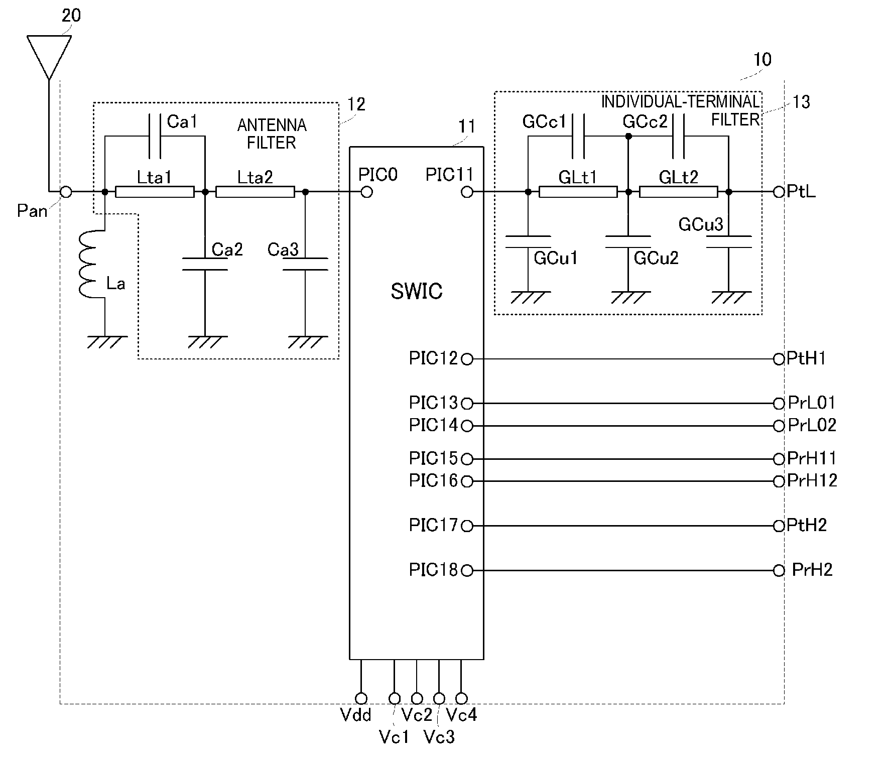
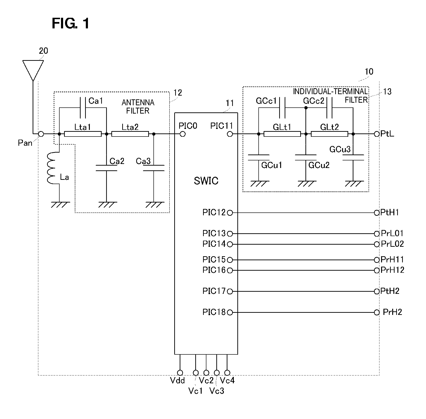
[0028]A high-frequency module according to a first preferred embodiment of the present invention is described below with reference to the drawings. FIG. 1 is a circuit diagram illustrating the configuration of a high-frequency module 10 of the first preferred embodiment.

[0029]The high-frequency module 10 preferably includes a switch IC 11, an antenna filter 12, and an individual-terminal filter 13. The high-frequency module 10 preferably includes a multilayer body and circuit elements mounted on the top surface of the multilayer body. The switch IC 11 is preferably a surface mount IC, and is mounted on the top surface of the multilayer body. The antenna filter 12 and the individual-terminal filter 13 preferably include inductors and capacitors, for example. In this case, based on the configuration of the high-frequency module 10 and the required values of the circuit elements, many possible inductors and capacitors may preferably be defined by interlayer electrode patterns provided ...


PUM


Abstract

A high-frequency module includes a switch IC. An antenna filter is connected to a common terminal of the switch IC and arranged adjacent to an antenna. The antenna filter is a low-pass filter whose attenuation band includes higher harmonic frequency bands of GSM1800 / GSM1900 transmission signals and TDS-CDMA transmission signals. An individual-terminal filter is connected to one individual terminal of the switch IC. The individual-terminal filter is a low-pass filter whose attenuation band includes higher harmonic frequency bands of GSM850 / GSM900 transmission signals.

Description

BACKGROUND OF THE INVENTION[0001]1. Field of the Invention[0002]The present invention relates to a high-frequency module for transmitting and receiving a plurality of communication signals having different frequency bands that includes a switch integrated circuit (IC).[0003]2. Description of the Related Art[0004]Various types of high-frequency modules including switch ICs have been proposed. For example, Japanese Unexamined Patent Application Publication No. 2008-516494 discloses a high-frequency module including a switch IC including six individual terminals for a single common terminal connected to an antenna. Each of the six individual terminals of the switch IC is connected to one of a transmission circuit, a reception circuit, and a transmission / reception circuit used for a plurality of communication signals having different frequency bands. In the high-frequency module configured as described above, the switch IC is driven to switch the connection between the common terminal a...

Claims


Application Information

Patent Timeline
Patent Type & Authority Patents(United States)
IPC IPC(8): H04B1/18
CPCH04B1/44H04B1/18
Inventor UEJIMA, TAKANORI
Owner MURATA MFG CO LTD
Why Eureka
Try Eureka