Supercharge Your Innovation With Domain-Expert AI Agents!

Tuyere Branches for Hot Dip Coating Equipment

A technology of hot-dip plating and tuyere, applied in hot-dip plating process, coating, metal material coating process, etc., can solve the problems of large space requirement, damage to product quality, expensive production, etc.

Active Publication Date: 2021-05-25
THYSSENKRUPP STEEL EURO AG +1
View PDF5 Cites 0 Cited by
  • Summary
  • Abstract
  • Description
  • Claims
  • Application Information

AI Technical Summary

Problems solved by technology

However, such devices are relatively expensive to produce and have large space requirements
In addition, product quality is further compromised by the high saturation of zinc vapor in the gas atmosphere prior to immersion due to sealing
Furthermore, for maintenance work, the fixedly constructed device has to be completely disassembled or the tuyere branch has to be removed as a whole

Method used


Image

  • Tuyere Branches for Hot Dip Coating Equipment
  • Tuyere Branches for Hot Dip Coating Equipment
  • Tuyere Branches for Hot Dip Coating Equipment

Examples


Embodiment Construction

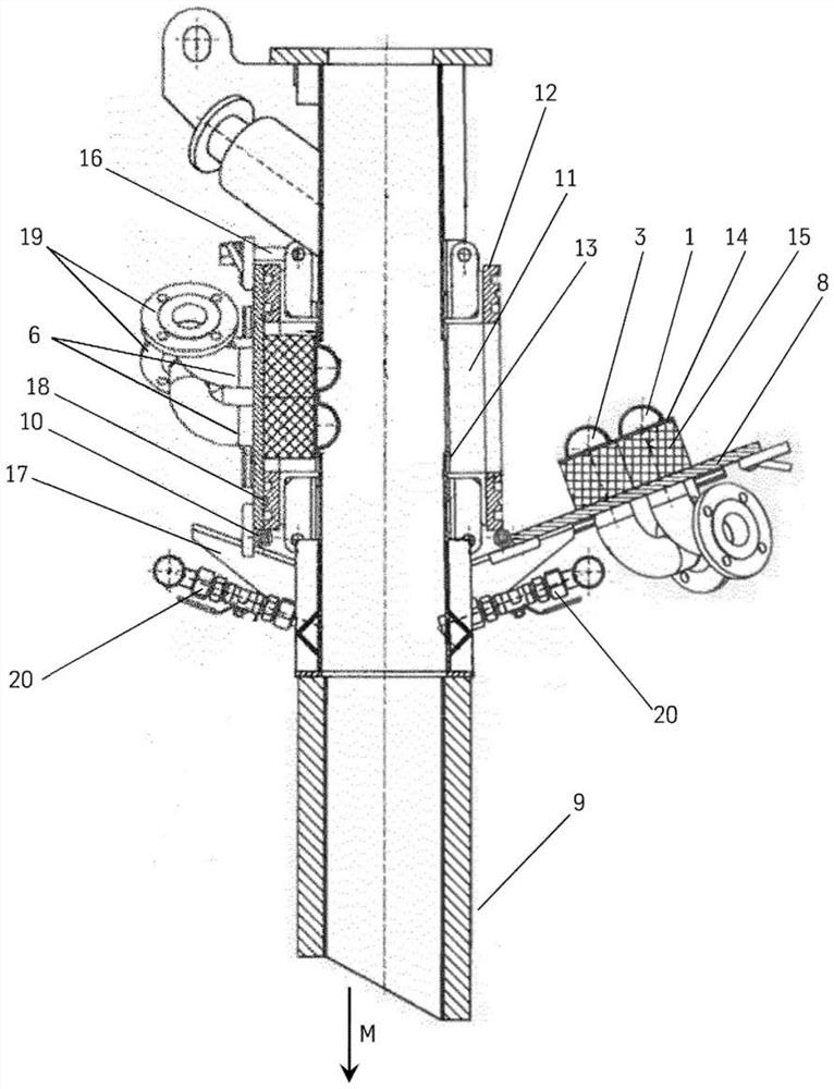
[0034] figure 1 An embodiment of the tuyere branch (9) according to the invention is shown from the side. Shown is the lower part of the tuyere branch (9) in which, in the installed state, the material flow direction (M) extends downwards from the top. The tuyere branch (9) is provided on both sides of the flat product not shown with the blowing unit (1) and the suction unit (3) extending across the width of the tuyere branch (9), where the left side is shown in the closed position , the right side is in the open position. The blowing unit (1) and the suction unit (3) are respectively arranged on the carrier plate (8).

[0035] The carrying plate (8) is movably fixed to the opposite plate (12) connected to the frame (11) by means of hinged joints (10). However, the articulated joint (10) can also be connected to the frame (11), the tuyere branch (9) or a plurality of said components. As shown, the hinged joint (10) is preferably arranged on the lower edge, viewed in the ma...


PUM

PropertyMeasurementUnit
diameteraaaaaaaaaa

Abstract

The invention relates to a tuyere branch (9) of a hot-dip coating plant for flat products (11), which extends from the outlet of a continuous furnace into the melt below the level of the coating bath and isolates the flat product from the surrounding environment , wherein at least one suction unit (3) and one blowing unit (1) are provided, it is characterized in that the blowing unit (1) and the suction unit (3) are arranged on a common bearing plate (8), carrying The plate (8) is connected to the tuyere branch (9) along the edge by at least one hinged joint (10), and the carrying plate (8) is movable into a closed position and an open position, in which the carrying plate (8 ) to close the opening on the tuyere branch (9).

Description

technical field [0001] The present application describes the so-called "snout" construction (English: snout), such as is commonly used in industrial practice as the main equipment part of hot-dip coating or flame coating equipment. Via this tuyere branch, the metal flat product, e.g. contact between the heat-treated surface and the ambient atmosphere. Background technique [0002] For example, equipment for continuous flame coating of steel strips consists of a continuous annealing furnace, a melting bath, a device for setting the thickness of the coating, and a downstream cooling device. The steel strip is continuously annealed in a continuous furnace, in which the continuous furnace is divided into chambers in which different treatments take place. These treatments include, for example, the adjustment of the desired mechanical properties of the base material by recrystallization of the steel. Furthermore, here, the iron oxides formed in the preheating zone are reduced. ...

Claims


Application Information

Patent Timeline
Patent Type & Authority Patents(China)
IPC IPC(8): C23C2/00C23C2/40
CPCC23C2/40C23C2/004
Inventor 斯里德哈·巴莱普米夏埃尔·彼得斯安德列亚斯·韦斯特费尔德约阿希姆·许尔斯特龙
Owner THYSSENKRUPP STEEL EURO AG
Features
  • R&D
  • Intellectual Property
  • Life Sciences
  • Materials
  • Tech Scout
  • Unparalleled Data Quality
  • Higher Quality Content
  • 60% Fewer Hallucinations
Learn More