Method for monitoring PDCCH, terminal and network equipment

A technology for network equipment and terminals, which is applied in the field of communication and can solve problems such as inability to configure UE

Active Publication Date: 2020-01-31
VIVO MOBILE COMM CO LTD
View PDF15 Cites 27 Cited by
  • Summary
  • Abstract
  • Description
  • Claims
  • Application Information

AI Technical Summary

Problems solved by technology

[0005] Embodiments of the present invention provide a method for monitoring PDCCH, a terminal and a network device, to solve the problem that the prior art does not limit the maximum processing capacity of the UE to bli

Method used


Image

  • Method for monitoring PDCCH, terminal and network equipment
  • Method for monitoring PDCCH, terminal and network equipment
  • Method for monitoring PDCCH, terminal and network equipment

Examples


Embodiment 1

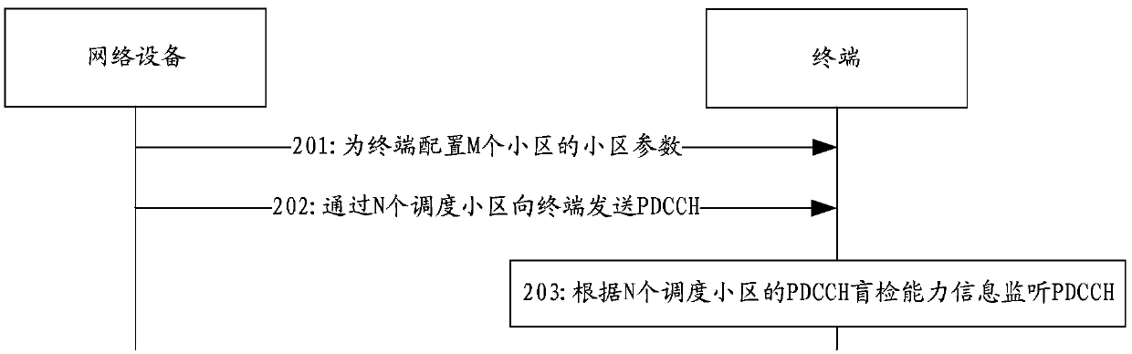
[0061] figure 2 It shows a schematic flowchart of a method for monitoring a PDCCH provided by an embodiment of the present invention, as shown in figure 2 As shown, the method for monitoring the PDCCH may include:

[0062] Step 201: The network device configures cell parameters of M cells for the terminal.

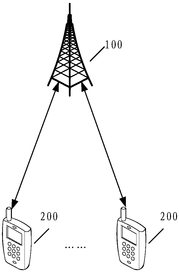
[0063] Correspondingly, the peer terminal receives the cell parameters sent by the network device to the terminal. Among them, the above-mentioned network equipment can be figure 1 A network device in the communication system shown, for example, a base station; the above-mentioned first terminal may be figure 1 Terminal equipment in the communication system shown.

[0064] Step 202: the network device sends the PDCCH to the terminal through the N scheduling cells.

[0065] Step 203: The terminal monitors the PDCCH according to the PDCCH blind detection capability information of the N scheduling cells.

[0066] In the embodiment of the present invention, the above-m...

Embodiment 2

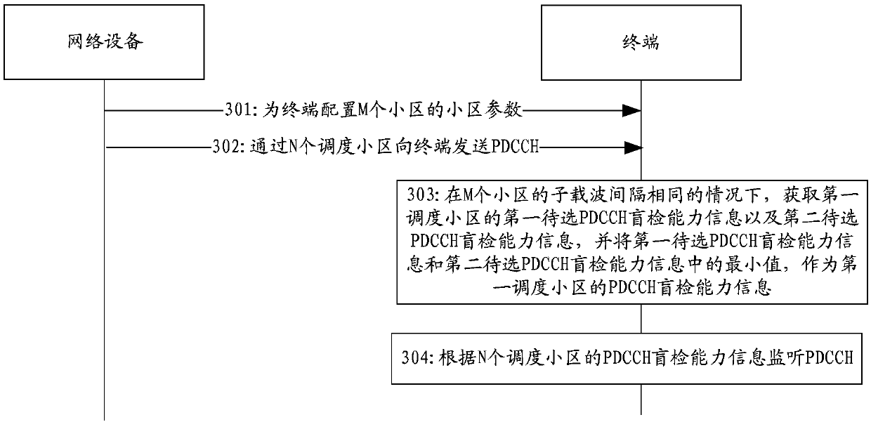
[0076] image 3 It shows a schematic flowchart of another method for monitoring a PDCCH provided by an embodiment of the present invention, as shown in image 3 As shown, the embodiment of the present invention is mainly aimed at the scenario where the subcarrier spacing of M cells is the same. In this scenario, the method for monitoring the PDCCH may include:

[0077] Step 301: The network device configures cell parameters of M cells for the terminal.

[0078] Step 302: the network device sends the PDCCH to the terminal through the N scheduling cells.

[0079] Step 303: When the subcarrier spacing of the M cells is the same, the terminal obtains the first candidate PDCCH blind detection capability information and the second candidate PDCCH blind detection capability information of the first scheduling cell, and stores the first candidate PDCCH The minimum value of the blind detection capability information and the second candidate PDCCH blind detection capability informatio...

Embodiment 3

[0103] Figure 4 It shows a schematic flow chart of another method for monitoring PDCCH provided by the embodiment of the present invention. The embodiment of the present invention can be applied to any cross-carrier scheduling scenario (that is, not only applicable to the scenario where the subcarrier spacing of M cells is the same , is also applicable to the scenario where the subcarrier spacing of the M cells is not the same). Such as Figure 4 As shown, the method for monitoring the PDCCH may include:

[0104] Step 401: The network device configures cell parameters of M cells for the terminal.

[0105] In the embodiment of the present invention, the above cell parameters further include: first priority information of N scheduling cells and / or second priority information of M cells.

[0106] Step 402: The network device sends the PDCCH to the terminal through the N scheduling cells.

[0107] Step 403: According to the first priority information / or the second priority in...


PUM


Abstract

The embodiment of the invention provides a method for monitoring a PDCCH, a terminal and network equipment, and relates to the technical field of communication, for solving the problem in the prior art that corresponding blind detection behaviors cannot be reasonably configured for UE (User Equipment) due to the fact that the maximum processing capacity of the UE for blind detection of PDCCH (Physical Downlink Control Channel) of a CC or a cell is not limited in a cross-carrier scheduling process. The method comprises the following steps: monitoring a PDCCH according to PDCCH blind detection capability information of N scheduling cells, wherein the N scheduling cells are cells in M cells configured for the terminal by the network equipment, and the M cells further comprise X scheduled cells; wherein the PDCCH blind detection capability information of the N scheduling cells is related to cell parameters of the M cells; wherein the PDCCH blind detection capability information of the N scheduling cells is used for indicating the maximum processing capability of blind detection of the PDCCH by the terminal in each scheduling cell or under the N scheduling cells in unit time; and wherein M and N are positive integers greater than or equal to 1, X is a positive integer greater than or equal to 0, and M = N + X.

Description

technical field [0001] The present invention relates to the field of communication technologies, and in particular to a method, terminal and network equipment for monitoring a Physical Downlink Control Channel (PDCCH). Background technique [0002] At present, the 5G (NR) system supports configuring multiple control resource sets (Control Resource Set, CORESET) and multiple search space sets for each carrier (Component Carrier, CC) or cell configured for the user equipment (User Equipment, UE), And the number of PDCCH candidates is flexibly configured for each search space set. [0003] In the prior art, for single-carrier scheduling or self-scheduling configuration under carrier aggregation (Carrier Aggregation, CA), the existing protocol stipulates the maximum processing capability of the UE for blind detection of the PDCCH of a CC or cell. The maximum processing capability Including: the maximum number of PDCCH candidates for the UE to perform blind detection on the PDCC...

Claims


Application Information

Patent Timeline
IPC IPC(8): H04W28/18H04W72/04H04L1/00
CPCH04W72/0453H04L1/0038H04W28/18H04L5/0053H04L5/001H04L1/0045H04W72/23Y02D30/70H04L1/00H04L41/0803H04W24/06
Inventor 纪子超
Owner VIVO MOBILE COMM CO LTD
Why Eureka
Try Eureka