Rotatable safety two-pin socket
A two-pin and socket technology, which is applied in the direction of flexible/rotatable wire connectors, bipolar connections, parts of connection devices, etc., can solve the problems of cumbersome and inconvenient daily use
- Summary
- Abstract
- Description
- Claims
- Application Information
AI Technical Summary
Problems solved by technology
Method used
Image

Examples
Embodiment 1
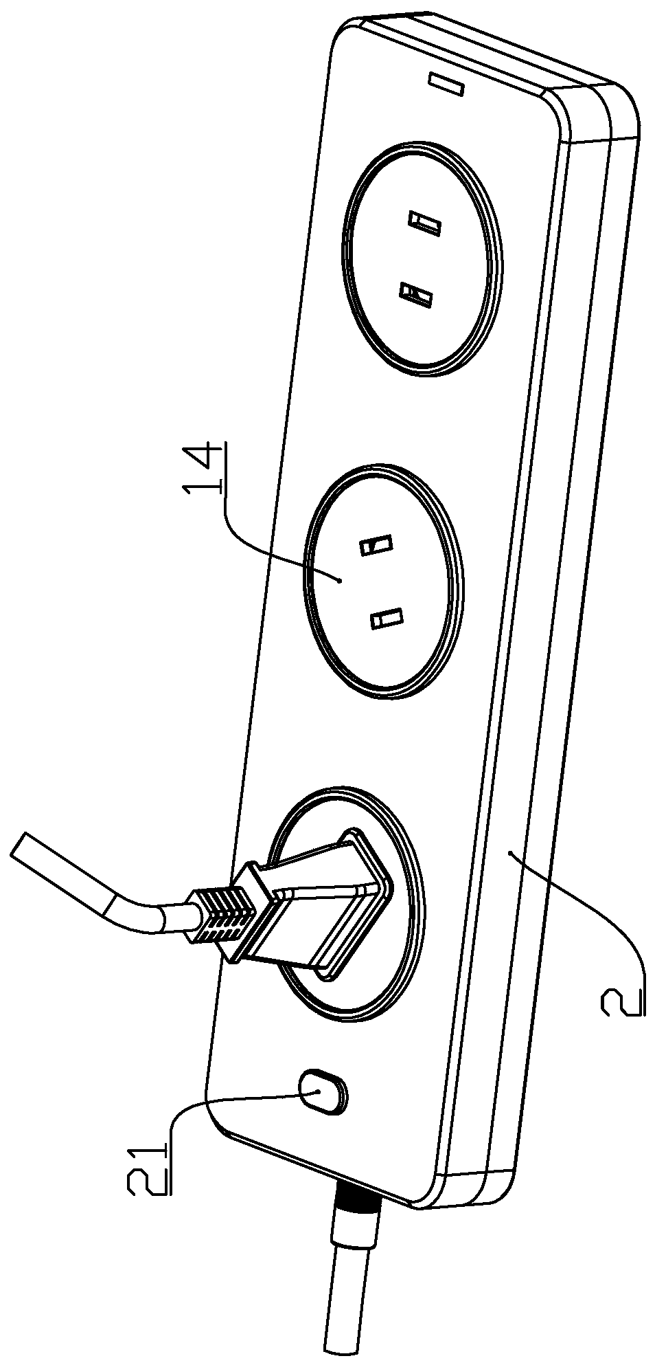
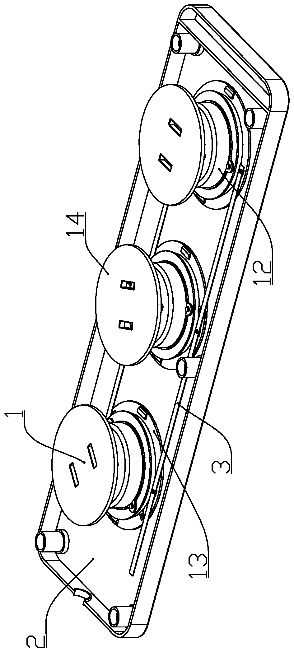
[0034] according to Figure 1 to Figure 9 As shown, a rotatable safety two-pin socket described in this embodiment includes a housing 2, one or more energizing components 1 that are rotatably connected in the housing 2 and are used to feed the energizing components 1 The transmission line for power supply is used to conduct the transmission line to the energization strip 3 of each of the energization components 1; since the transmission line includes a neutral line and a live wire, the energization strip 3 is two and connected to the neutral line and the live line respectively. connect.
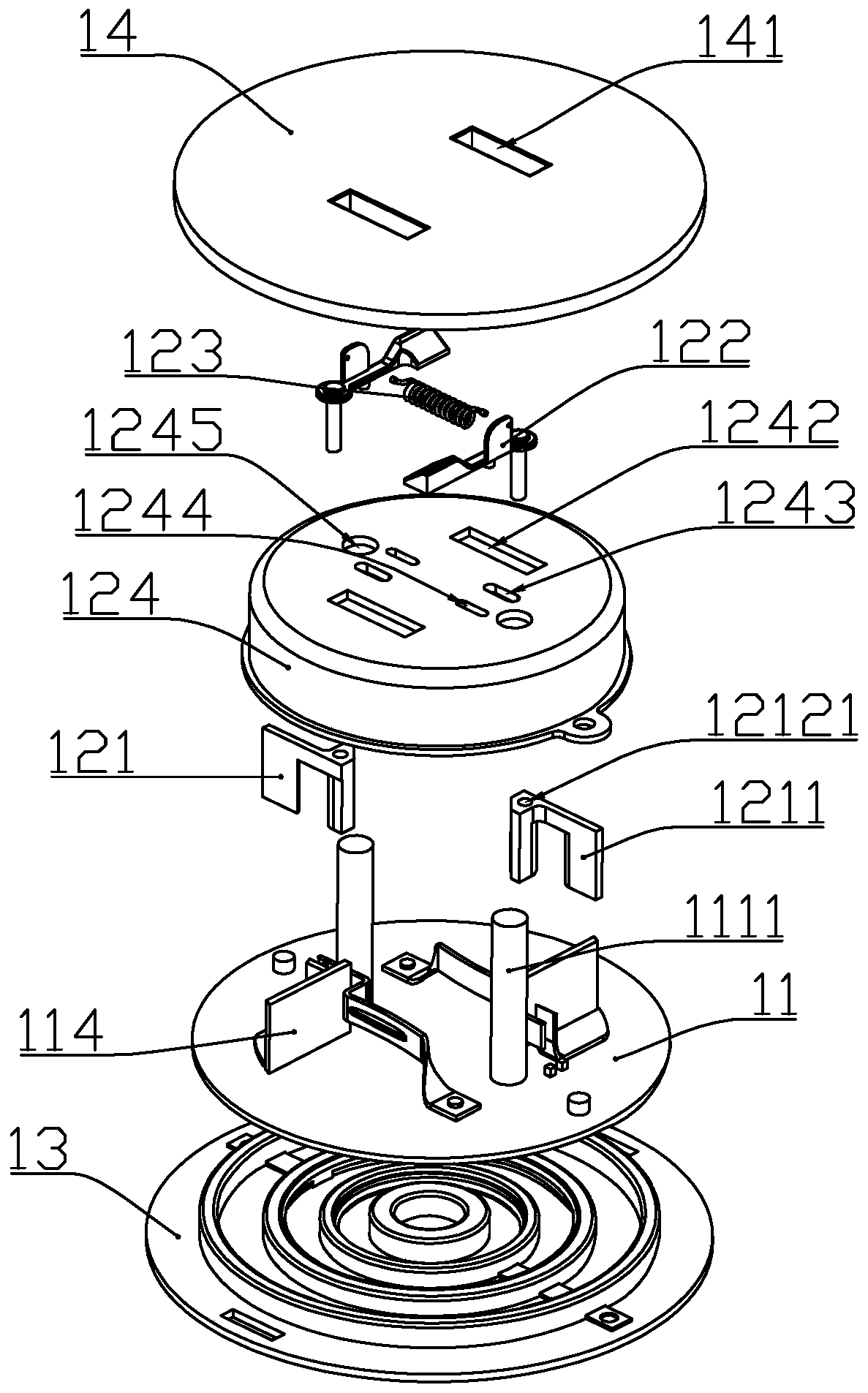
[0035] The energization assembly 1 includes an electrode mounting seat 13 fixedly connected to the inner bottom surface of the housing 2, a rotating connecting plate 11 rotatably connected to the upper end of the electrode mounting seat 13, and a safety component installed on the rotating connecting plate 11. 12 and the rotating plate 14 that is rotatably connected to the upper end surface o...
Embodiment 2
[0050] combine Figure 10 As shown, the difference between this embodiment and Embodiment 1 is that the spring 123 is installed in the following different forms:
[0051] The fixing column 1111 is located at the upper end of the electrode sheet mounting plate 111 and is located at the side of the moving part 122 away from the center of the safety cover 124; Between the adjacent spring mounting plates 1222; the spring 123 is under compression in the initial state.
[0052] The spring 123 is further compressed when the pin is inserted, and stretches to reset the moving part 122 when the pin is pulled out.
Embodiment 3
[0054] combine Figure 11 As shown, the difference between this embodiment and Embodiment 1 is that the elastic reset member is changed to a magnetic reset member.
[0055] The magnetic resetting parts are magnets 125 fixedly connected to the two moving parts 122 respectively; the magnets 125 are arranged facing each other and attract each other.
[0056] Further, one of the magnets 125 is replaced by iron sheet or other magnetically permeable materials.
[0057] The two magnets 125 or the magnet 125 and the iron sheet (other magnetic material) are separated by inserting the pins, and the moving part 122 is reset by magnetic attraction when the pins are pulled out.
PUM
 Abstract
Description
Claims
Application Information