Fastening part screwing-in machine for building steel plate abut joint

A technology for building steel plates and components, which is applied in the field of fastening parts screw-in machines for butt joints of building steel plates, can solve the problems of low safety, easy falling, and difficulty for workers to maintain balance, and achieve high safety and convenient operation for workers Effect

Active Publication Date: 2020-02-07
滁州力天建筑工程有限公司
View PDF6 Cites 4 Cited by
  • Summary
  • Abstract
  • Description
  • Claims
  • Application Information

AI Technical Summary

Problems solved by technology

[0005] In order to overcome the shortcomings that workers sometimes need to work at high places, and workers need both hands to connect two steel plates together, it is difficult for workers to maintain balance, they are easy to fall, and the safety is not high. The technical problem of the present invention is to provide a A screw-in machine for fastening parts for butt joints of building steel plates that is convenient for workers to maintain balance and has high safety

Method used


Image

  • Fastening part screwing-in machine for building steel plate abut joint
  • Fastening part screwing-in machine for building steel plate abut joint
  • Fastening part screwing-in machine for building steel plate abut joint

Examples


Embodiment 1

[0028] A screw-in machine for fastening parts for building steel plate butt joints, such as figure 1 As shown, it includes a handle 1, a fixed plate 2, a placement component 7, a rotating component 8 and a push component 9, the left side of the handle 1 is fixedly connected with the fixed plate 2, and the front side of the handle 1 is provided with a placement component 7, and the placement component 7 is used to place the nut, and the placing assembly 7 is provided with a rotating assembly 8, which is used to drive the nut to rotate, and the fixed plate 2 is provided with a pushing assembly 9, which is used to push the bolt.

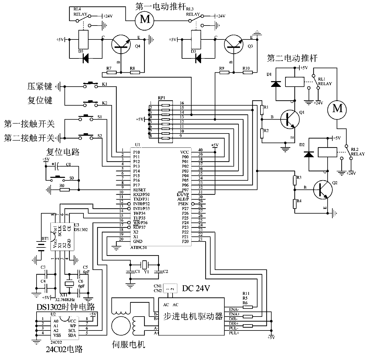
[0029] Such as figure 1 , Figure 6 and Figure 7 As shown, it also includes a control module, a compression key 4 and a reset key 6. The top of the handle 1 is provided with a compression key 4 and a reset key 6. The compression key 4 is located on the right side of the reset key 6. The compression key 4 and the reset key The keys 6 are electrically...

Embodiment 2

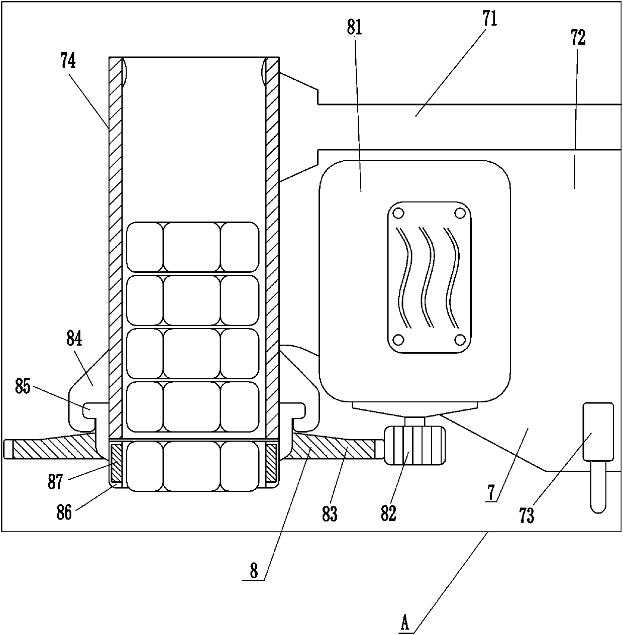
[0032] On the basis of Example 1, such as figure 1 and figure 2 As shown, the placement assembly 7 includes a first electric push rod 71, a mounting plate 72, a first contact switch 73 and a circular tube 74, the first electric push rod 71 is installed on the front side of the handle 1, and the first electric push rod 71 The push rod is L-shaped, the bottom of the first electric push rod 71 is connected with a mounting plate 72, the front side of the mounting plate 72 is provided with a first contact switch 73, and the left end of the first electric push rod 71 is connected with a circular tube 74 for placing nuts .

[0033]The worker puts the nut into the circular tube 74, the nut at the bottom is sucked by the rotating assembly 8, and then presses the compression key 4, the control module controls the pushing assembly 9 to work for 2 seconds, and the pushing assembly 9 drives the bolt to move upwards, so that the bolt After 2 seconds, the control module controls the pushi...

Embodiment 3

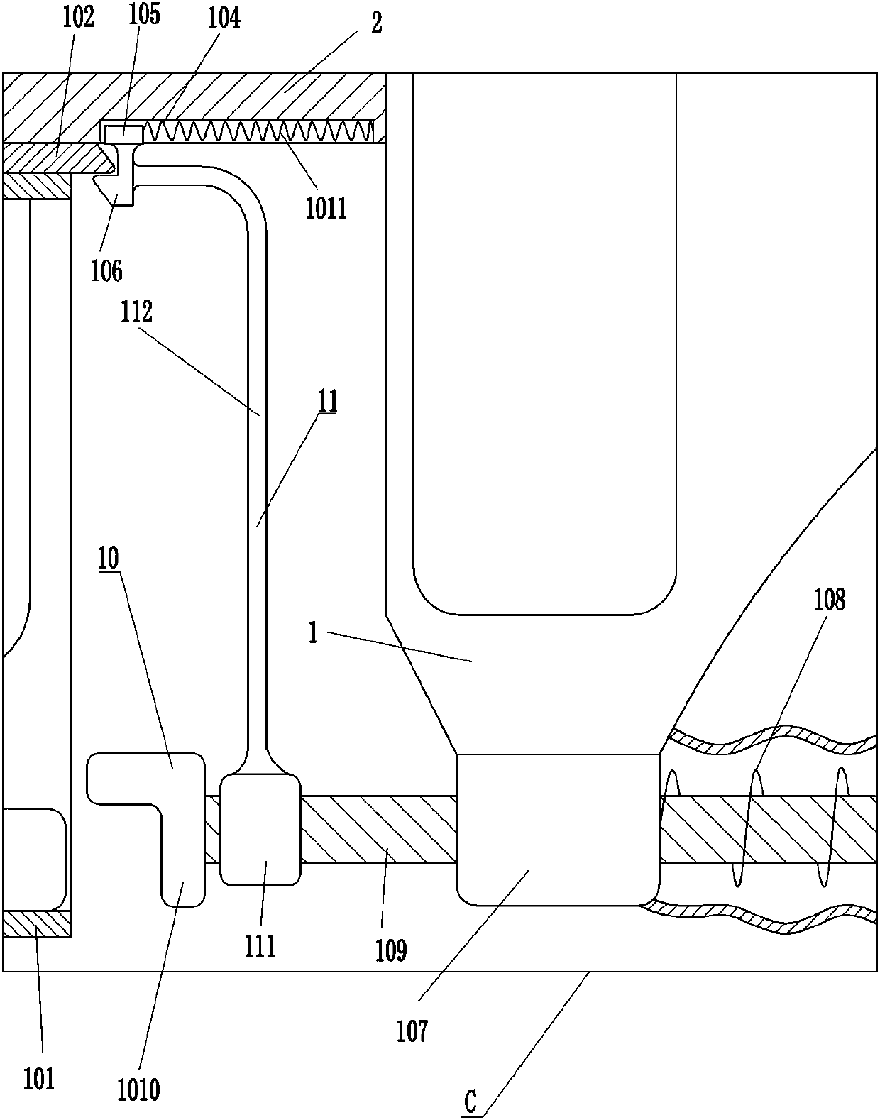
[0039] On the basis of Example 2, such as figure 1 , image 3 , Figure 4 and Figure 5 As shown, an automatic loading assembly 10 is also included, and the automatic loading assembly 10 includes a blanking frame 101, a wedge-shaped plate 102, a clip bar 103, a guide block 105, a hook 106, a sliding sleeve 107, a first spring 108, a slide bar 109. The push plate 1010 and the second spring 1011, the left side of the bottom of the fixed plate 2 is connected with a clip 103, the right side of the bottom of the fixed plate 2 is provided with a guide chute 104, and the sliding type in the chute 104 is provided with a guide block 105 A second spring 1011 is connected between the guide block 105 and the inner wall of the chute 104, the hook 106 is connected to the guide block 105, a wedge-shaped plate 102 is stuck between the clip bar 103 and the hook 106, and the bottom of the wedge-shaped plate 102 is fixed with a The blanking frame 101 of the bolt, the bottom of the handle 1 is...


PUM


Abstract

The invention relates to a fastening part screwing-in machine, in particular to a fastening part screwing-in machine for building steel plate abut joint. A worker can be conveniently kept balanced, and safety is high. The fastening part screwing-in machine for building steel plate abut joint comprises a holding handle, a fixed plate, a placing assembly and the like. The side face of the holding handle is fixedly connected with the fixed plate, the placing assembly is placed on the holding handle, a rotating assembly drives a nut to rotate clockwise, a pushing assembly can drive a bolt to moveupwards, the bolt can be screwed in the nut, two steel plates are connected, accordingly, a worker can finish the operation through the single hand, the worker can be conveniently kept balanced, and safety is high. Through an automatic loading assembly, the bolt can be pushed to an L-shaped plate in a guide sleeve, automatic loading is achieved, and the machine is rapid and convenient.

Description

technical field [0001] The invention relates to a fastening component screw-in machine, in particular to a fastening component screw-in machine for building steel plate butt joints. Background technique [0002] The steel plate is a flat steel material that is poured with molten steel and pressed after cooling. The steel plate is mainly used in the construction industry. In the construction industry, the steel plate plays a vital role. In the construction process, because the steel plate is plate-shaped, it needs The two steel plates are connected by fastening components such as bolts and nuts. [0003] Now the general workers pass the bolts through the steel plate with one hand, screw the nuts onto the bolts with the other hand, and connect the two steel plates together. Workers sometimes need to work at high places, and the workers need both hands to connect the two steel plates together. Therefore, It is difficult for workers to keep their balance, they are easy to fall,...

Claims


Application Information

Patent Timeline
Patent Type & Authority Applications(China)
IPC IPC(8): B25B27/14
CPCB25B27/143
Inventor 李跃
Owner 滁州力天建筑工程有限公司
Why Eureka
Try Eureka