Intelligent and safe counter lock device

A safe and intelligent technology, applied in the field of locomotive locks, can solve the problems of no electric lock, poor safety, damage to the anti-lock structure, etc., and achieve the effect of labor-saving and easy operation, preventing damage and reducing impact force.

Pending Publication Date: 2020-02-11
上海勃傲自动化系统有限公司
View PDF0 Cites 1 Cited by
  • Summary
  • Abstract
  • Description
  • Claims
  • Application Information

AI Technical Summary

Problems solved by technology

[0004] The invention provides an intelligent safety anti-lock device, which aims to solve the problem that the anti-lock structure of the original mechanical lock is connected with the transmission assembly. After being hit, the impact force will be transmitted to the transmission assembly, which will make the transmission screw The existing electric locks do not have motor overload protection. When the motor is not working normally, it will cause damage to the anti-lock structure. The locomotive lock tongue has a simple structure and poor operating feeling. Rotating and falling, the handle will rotate up during the process of the bolt spring stretching, which is a problem of poor safety

Method used


Image

  • Intelligent and safe counter lock device
  • Intelligent and safe counter lock device
  • Intelligent and safe counter lock device

Examples


Embodiment Construction

[0028] In order to make the object, technical solution and advantages of the present invention clearer, the present invention will be described in further detail below in conjunction with the accompanying drawings and embodiments. It should be understood that the specific embodiments described here are only used to explain the present invention, not to limit the present invention.

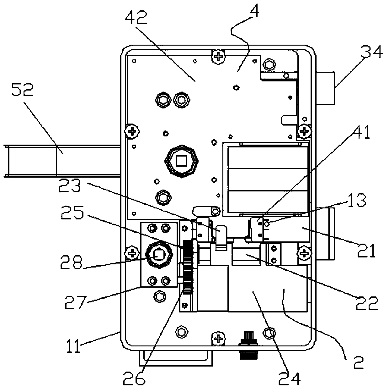
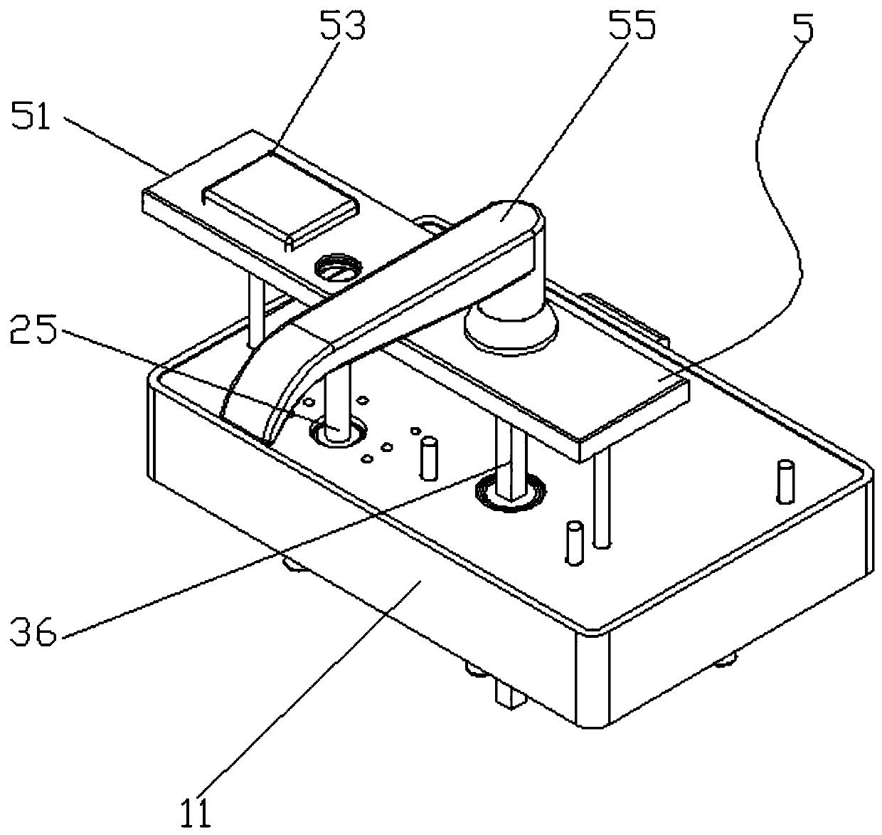
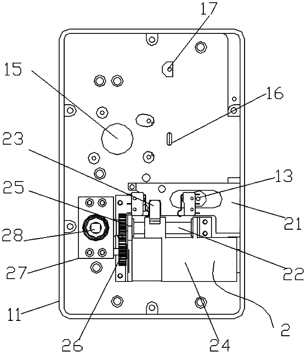
[0029] see Figure 1-7 , the present invention provides a technical solution: an intelligent safety anti-lock device, including a housing assembly 1 and an anti-lock assembly 2, the housing assembly 1 includes a housing 11, an anti-lock shaft hole 12, an anti-lock limit post 13, a bearing slot 15, The first clamping plate 16 and the second clamping plate 17, the lower surface of the inner cavity of the housing 11 is provided with an anti-lock shaft hole 12, and the side of the housing 11 located at the anti-lock shaft hole 12 is provided with an anti-lock limit post 13, and the bottom of the inner ...


PUM


Abstract

The invention is suitable for the technical field of locomotive locks and provides an intelligent and safe counter lock device. The intelligent and safe counter lock device comprises a shell assemblyand a counter lock assembly. The shell assembly comprises a shell, a counter lock shaft hole and a counter lock limiting pillar, wherein the counter lock shaft hole is formed in the lower surface of an inner cavity of the shell. Due to the fact that a motor and a counter lock screw rod are arranged, the motor rotates through a motor gear at an output end, the motor gear is connected with a screw rod gear in an engaged manner, the counter lock screw rod is driven to rotate, a transmission sliding block slides in the counter lock screw rod, a counter lock spring bolt is pushed to slide, counterlock is controlled through the motor, and therefore operation is more convenient. Due to the arrangement of a clamping structure of the transmission sliding block and the counter lock spring bolt, theimpact force exerted on the counter lock spring bolt can be effectively reduced, unloading force protection is conducted on a transmission structure of the counter lock assembly, and the transmissionstructure is prevented from being damaged. Due to the fact that a limiting circuit breaker is arranged, the phenomenon that the motor is overloaded, and the counter lock structure is damaged is prevented, and overload protection on the motor is achieved.

Description

technical field [0001] The invention belongs to the technical field of locomotive locks, and in particular relates to an intelligent safety anti-lock device. Background technique [0002] Electronic door locks emerged with the development of electronic technology. They are incomparable to mechanical locks in terms of convenience of use, prevention of illegal opening, and intelligent management. Therefore, they are widely used in industries with high safety requirements. The common ones are mainly magnetic cards, IC cards, TM cards, and radio frequency card electronic door locks. [0003] The anti-lock structure of the original mechanical lock is connected with the transmission component. After being hit, the impact force will be transmitted to the transmission component, which will cause damage to the transmission screw. The existing electric lock has no motor overload protection. When the motor is not working normally, it will cause damage to the anti-lock structure. The o...

Claims


Application Information

Patent Timeline
Patent Type & Authority Applications(China)
IPC IPC(8): E05B17/20E05B47/00E05B49/00E05B9/00E05B15/10E05B15/00E05B15/04
CPCE05B9/00E05B15/00E05B15/0013E05B15/04E05B15/10E05B17/20E05B47/0012E05B49/00E05B2015/0406E05B2015/0448E05B2047/002
Inventor 彭超高冉谭乐章伟云汪清
Owner 上海勃傲自动化系统有限公司
Why Eureka
Try Eureka