Buffering type steel wire rope stranding device

A technology of steel wire rope and buffer sleeve, which is applied in the field of buffer type wire rope twisting device, which can solve the problems of inconvenient operation efficiency and the inability to change the number of steel wires for twisting strands, and achieve the effects of flexible use, wide range of use, and avoiding bump damage

Pending Publication Date: 2020-02-14
江苏艾可森钢绳有限公司
0 Cites 0 Cited by

AI-Extracted Technical Summary

Problems solved by technology

The steel wire rope is first twisted into strands by multi-layer steel wires, and then twisted into a helical rope by a certain number of strands around the rope core. The number of twisted wires canno...

Abstract

The invention discloses a buffering type steel wire rope stranding device. The buffering type steel wire rope stranding device comprises a base, a wire frame, a stranding mechanism, a driving mechanism, a wire routing pipe, a wire pressing mold, a winding roller and a buffering mechanism. The buffering mechanism is additionally arranged, a buffering elastic body is used for performing telescopic movement in a buffering sleeve through a telescopic column, and when a wire routing ring at the outer end of the telescopic column is pulled by a steel wire, the telescopic column is buffered through the buffering elastic body, so that the problem of collision damage of the steel wire is avoided, and the quality of the steel wire is improved.

Application Domain

Rope making machines

Technology Topic

Image

  • Buffering type steel wire rope stranding device
  • Buffering type steel wire rope stranding device
  • Buffering type steel wire rope stranding device

Examples

  • Experimental program(1)

Example Embodiment

[0019] The content of the present invention will be further described in detail below in conjunction with the accompanying drawings.
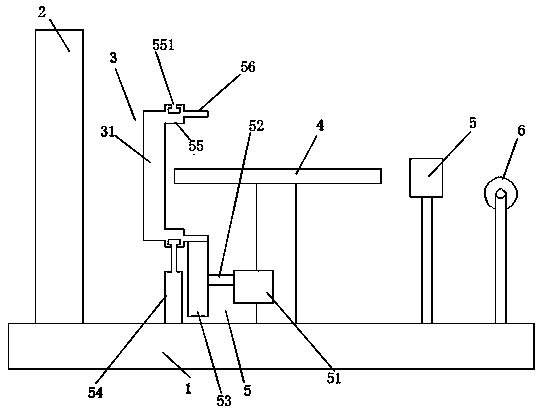
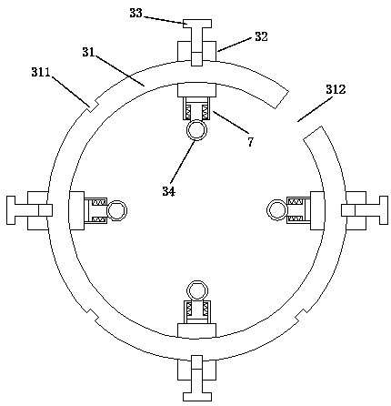
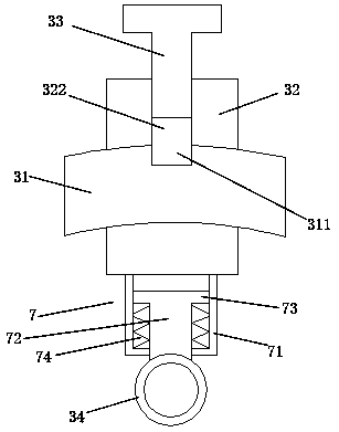
[0020] like Figures 1 to 5 As shown, a buffer type wire rope twisting device includes a base 1, a wire frame 2, a twisting mechanism 3, a driving mechanism 5, a wire pipe 4, a crimping die 5, a winding roller 6, and a buffer mechanism 7. The wire stand 2, the strand twisting mechanism 3, the cable routing pipe 4, the crimping die 5, and the winding roller 6 are sequentially installed on the base 1; the strand twisting mechanism 3 includes a rotating ring 31, a sliding socket block 32. Lock screw 33, wire routing ring 34; the drive mechanism 5 is installed on the base 1; the drive mechanism 5 controls the rotation of the rotating ring 31; the rotating ring 31 is provided with an insertion The gap 312 is convenient for the socket entry of the sliding socket block 32; a plurality of locking grooves 311 are uniformly distributed around the outside of the rotating ring 31; the sliding socket block 32 is provided with socket grooves 321; The outer end of the socket groove 321 is provided with a connected thread groove 322; one side of the socket groove 321 is provided with a connected penetration port 323; the threaded groove 322 is threadedly connected to a locking screw 33; The above-mentioned sliding socket block 32 penetrates through the insertion gap 323 from the insertion gap 312 of the rotating ring 31, and the sliding socket block 32 is slidably socketed on the rotating ring 31 through the socket groove 321 to make an arc movement; A plurality of sliding sleeve blocks 32 are slidably socketed on the rotating ring 31; the locking screw 33 rotates through the threaded groove 322 and is inserted into the locking groove 311 connected to the rotating ring 31; the buffer mechanism 7 includes a buffer Sleeve 71, telescopic column 72, limit ring 73, buffer elastic body 74; the buffer sleeve 71 is installed on the inner end of the sliding socket block 32; the inner end of the telescopic column 72 extends into the buffer sleeve Inside the barrel 71; the outer end of the telescopic column 72 extends to the outside of the buffer sleeve 71; the outer end of the telescopic column 72 is installed with the wiring ring 34; the inner end of the telescopic column 72 is installed with a limit ring 73; The limit ring 73 fits and slides around the inner wall of the buffer sleeve 71; the buffer elastic body 74 is sleeved on the telescopic column 72; the two ends of the buffer elastic body 74 respectively elastically abut Press between the limit ring 73 and the inner side wall of the buffer sleeve 71 .
[0021] like Figures 1 to 5 As shown, further preferably, the drive mechanism 5 includes a drive motor 51, a rotating shaft 52, a drive gear 53, a positioning ring body 55, a driven gear ring 56, and a positioning rod 54; one side of the rotating ring 31 The positioning ring body 55 is installed; the driven gear ring 56 is installed on the outside of the positioning ring body 55; the driving motor 51 is installed below the wiring pipe 4; the driving motor 51 is connected to the rotating shaft 52; The rotating shaft 52 is connected to the driving gear 53; the driving gear 53 is engaged with the driven gear ring 56; the lower end of the positioning rod 54 is fixed on the base 1, and the upper end is connected to the lower side of the positioning ring body 55; the positioning ring The body 55 is rotatably clamped on the upper end of the positioning rod 54 . Further, the positioning ring body 55 is provided with a rotating clamping ring groove 551; the upper end of the positioning rod 54 is provided with a rotating clamping plate; the positioning ring body 55 is rotated and clamped through the rotating clamping ring groove On the rotating clamping plate at the upper end of the positioning rod 54 ; the rotating clamping plate is in an arc-shaped structure. Further, the sliding socket block 32 is provided with an elastic pressing member 36 and a pressing plate 35; the pressing plate 35 is installed in the socket groove 321 of the sliding socket block 32; the pressing plate 35 There is a piercing port 351 in the middle; the upper end of the pressing plate 35 is connected to the upper end of the sleeve groove 321 through a plurality of elastic pressing pieces 36; Connected to the outer surface of the rotating ring 31 ; the locking screw 33 rotates through the threaded groove 322 and the threaded port 351 and then inserted into the locking groove 311 of the rotating ring 31 . Further, the said pressing plate 35 is in an arc-shaped structure that fits the outer surface of the rotating ring 31; combined arc structure. Further, the said cable conduit 4 is vertically distributed to the center of the rotating ring 31 .
[0022] The present invention adds a buffer mechanism 7, and the telescopic column 72 uses the buffer elastic body 74 in the buffer sleeve 71 to perform telescopic movement. The body 74 realizes buffering, thus avoiding the problem of steel wire bumping and damage, and improving the quality of the steel wire; the present invention changes the structure of the traditional twisting disc, and adds a twisting mechanism 3, through the sliding sleeve block 32 from the rotating ring 31 The insertion gap 312 penetrates, and the sliding socket block 32 is slidably socketed on the rotating ring 31 through the socket groove 321 to make an arc movement, so that a plurality of sliding socket blocks 32 are slidably socketed on the rotating ring 31, and then Rotate the locking screw 33 through the thread groove 322 and insert it into the locking groove 311 of the rotating ring 31 to realize the positioning of the sliding socket block 32 and the rotating ring 31, and install the routing ring 34 on the sliding socket block 32 In this way, the number of wire rings 34 can be changed by changing the number of sliding socket blocks 32 slidingly sleeved on the rotating ring 31, so that the number of steel wires passing through the wire ring 34 can be changed, and the application range is wide , Use more flexibly.
[0023] The above descriptions are only preferred embodiments of the present invention, and are not intended to limit the present invention. Any modifications, equivalent replacements, improvements, etc. made within the spirit and principles of the present invention shall be included in the scope of the present invention. within the scope of protection.

PUM

no PUM

Description & Claims & Application Information

We can also present the details of the Description, Claims and Application information to help users get a comprehensive understanding of the technical details of the patent, such as background art, summary of invention, brief description of drawings, description of embodiments, and other original content. On the other hand, users can also determine the specific scope of protection of the technology through the list of claims; as well as understand the changes in the life cycle of the technology with the presentation of the patent timeline. Login to view more.

Similar technology patents

Roll type electrodialyzer

PendingCN114849477AEasy to carryAvoid bump damageGeneral water supply conservationElectrodialysisElectrodialysisStructural engineering
Owner:ZHEJIANG LVCHUANG BIOTECHNOLOGY CO LTD

Portable boiler wastewater component detection device

PendingCN114236070AAvoid bump damageEasy to grab and useTesting waterLinear motorElectric machine
Owner:刘杰

Classification and recommendation of technical efficacy words

  • Quality improvement
  • Avoid bump damage

Monodisperse core/shell and other complex structured nanocrystals and methods of preparing the same

ActiveUS20050129947A1Narrow size distributionQuality improvementMaterial nanotechnologyFrom normal temperature solutionsChemistrySemiconductor nanostructures
Owner:THE BOARD OF TRUSTEES OF THE UNIV OF ARKANSAS

Portable high vegetable and fruit picking device

ActiveCN108076819AAvoid bump damagePicking devicesEngineeringPower output
Owner:HEXIAN LVYUAN VEGETABLE PLANTATION CO LTD

Lubricating oil-way of engine cylinder assembly

InactiveCN1786449AAvoid bump damageBeautiful structural designCylinder headsCylindersCylinder blockMotor oil
Owner:CHERY AUTOMOBILE CO LTD

Rainproof and sunshield multifunctional two-wheeled vehicle mobile phone holder

InactiveCN107813889AEnsure electricity safetyAvoid bump damageArticle supporting devicesOther supporting devicesElectrical and Electronics engineeringMobile phone
Owner:湖南海得利网络科技有限公司
Why Eureka
Try Eureka