

Makeup mirror lighting control method and system, terminal equipment and makeup mirror
A technology of terminal equipment and lighting control, applied in the direction of electrical components, etc., can solve problems such as unpredictable makeup effects, and achieve real-time monitoring of light intensity, zero hardware costs, and high data accuracy.
- Summary
- Abstract
- Description
- Claims
- Application Information
AI Technical Summary
Problems solved by technology
Method used
Image

Examples
no. 1 example
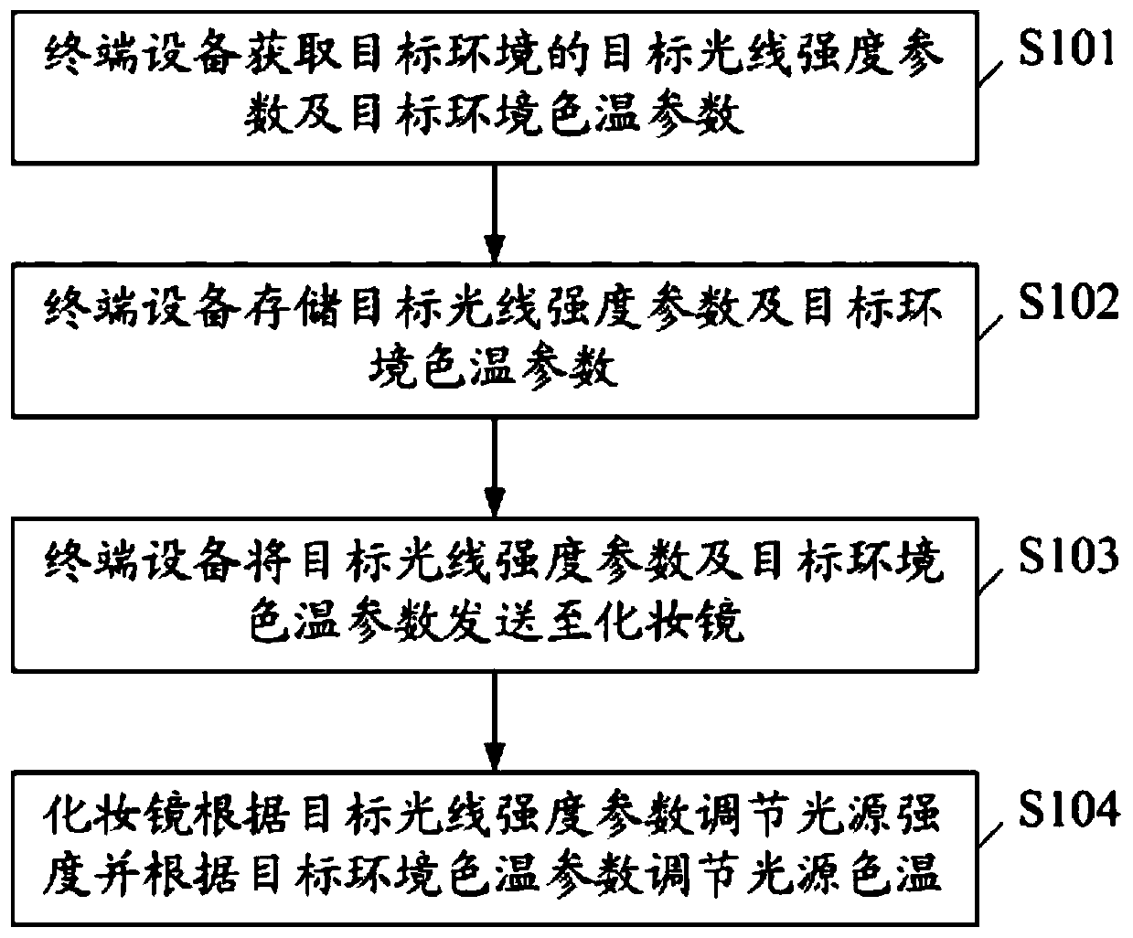
[0029] see figure 1 , figure 1 It shows the flow chart of the first embodiment of the lighting control method of the vanity mirror of the present invention, which includes:
[0030] S101. The terminal device acquires a target light intensity parameter and a target environment color temperature parameter of a target environment. There is a one-to-one correspondence between the target light intensity parameter and the target environment color temperature parameter.
[0031] Specifically, the terminal device obtains the target light intensity parameter of the target environment through its built-in light sensor. When working, the user only needs to point the light sensor to the light source in the target environment to obtain the light intensity parameters of the target environment.
[0032] It should be noted that the terminal device monitors the built-in light sensor in real time, and the light sensor monitors changes in ambient light in real time. When the light sensor dete...
no. 2 example
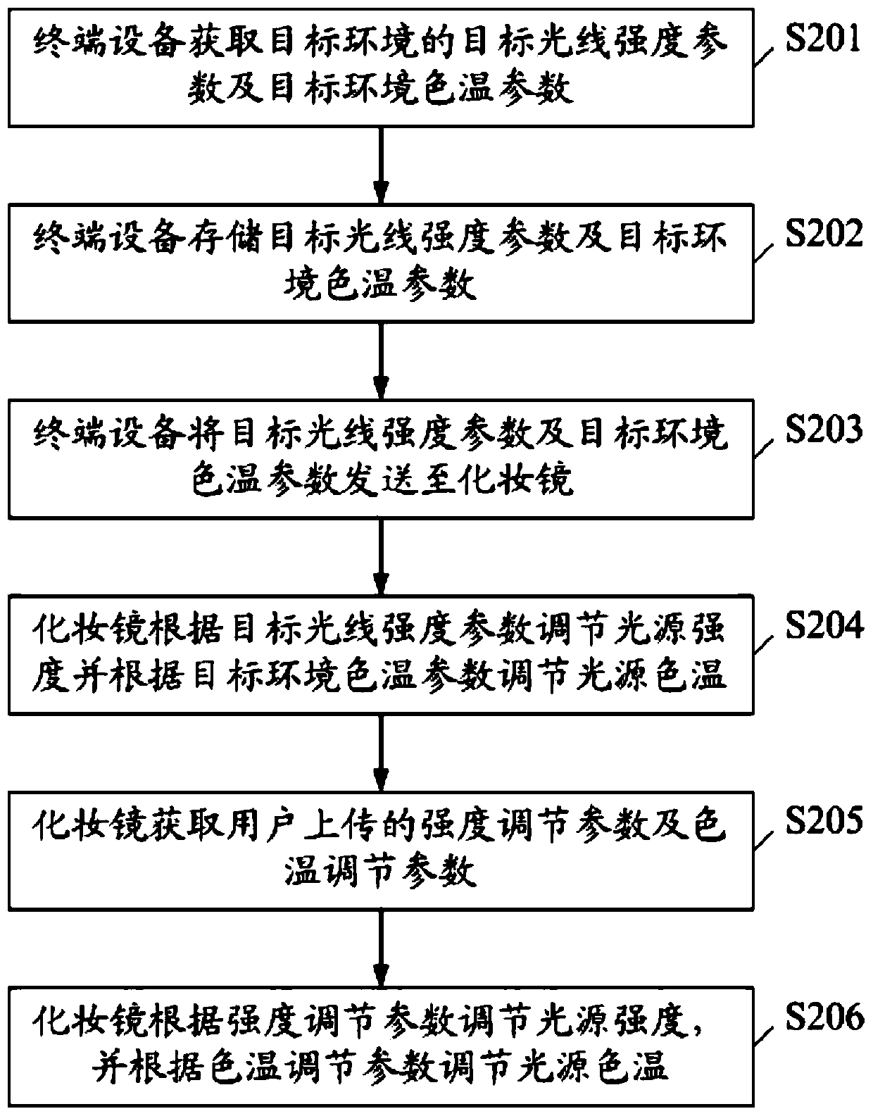
[0061] see figure 2 , figure 2 It shows the flow chart of the second embodiment of the lighting control method of the vanity mirror of the present invention, which includes:
[0062] S201. The terminal device acquires a target light intensity parameter and a target environment color temperature parameter of a target environment.
[0063] S202. The terminal device stores the target light intensity parameter and the target environment color temperature parameter.
[0064] S203. The terminal device sends the target light intensity parameter and the target environment color temperature parameter to the vanity mirror.
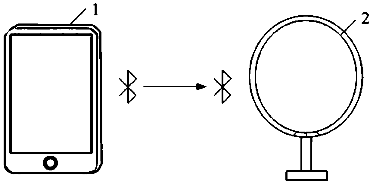
[0065] The terminal device can send the target light intensity parameter and the target environment color temperature parameter to the vanity mirror through Bluetooth.
[0066] S204. The vanity mirror adjusts the intensity of the light source according to the target light intensity parameter and adjusts the color temperature of the light source according to the...
PUM
 Abstract
Description
Claims
Application Information