Template matching implementation device and method based on FPGA
A technology of template matching and implementation method, applied in the field of image processing, can solve the problems of long calculation time, large volume, limited application scenarios of template matching, etc., and achieve the effect of reducing power consumption of equipment
Active Publication Date: 2020-02-18
易思维(杭州)科技有限公司
View PDF6 Cites 2 Cited by
- Summary
- Abstract
- Description
- Claims
- Application Information
AI Technical Summary
Problems solved by technology
Due to the huge amount of template matching calculations, it is mostly implemented in PCs or industrial computers, which has the disadvantages of high cost, large volume, and high power consumption, which limits the
Method used
View moreImage
Smart ImageViewing Examples

Examples
 PUM
 Abstract
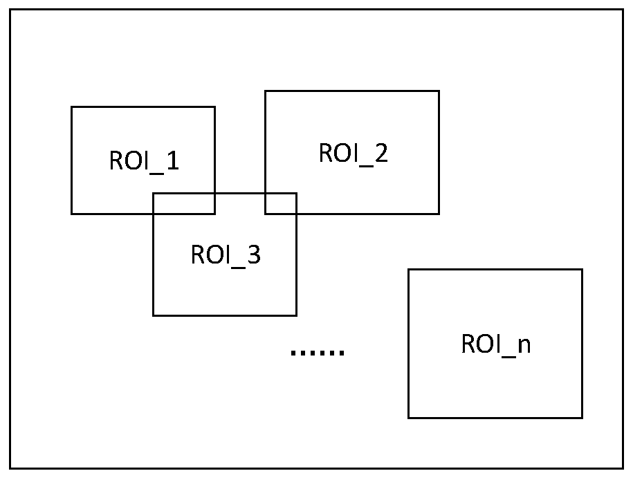
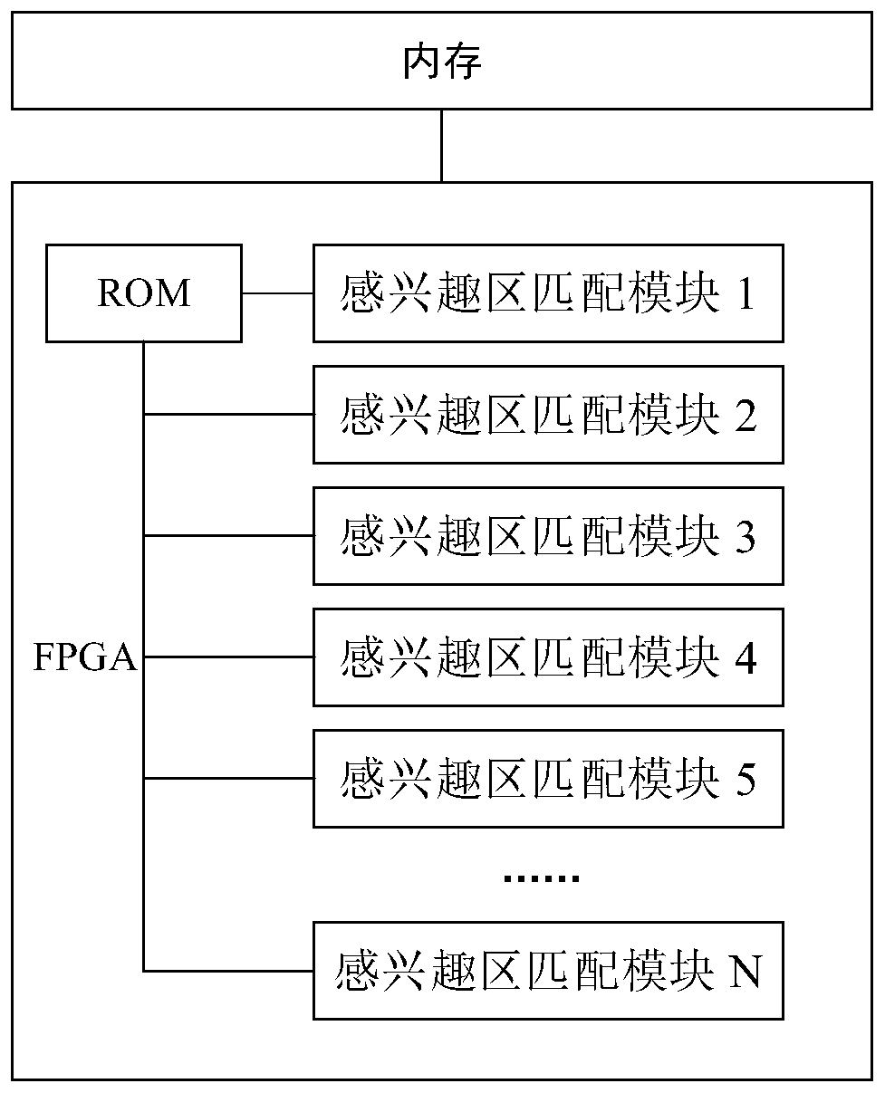
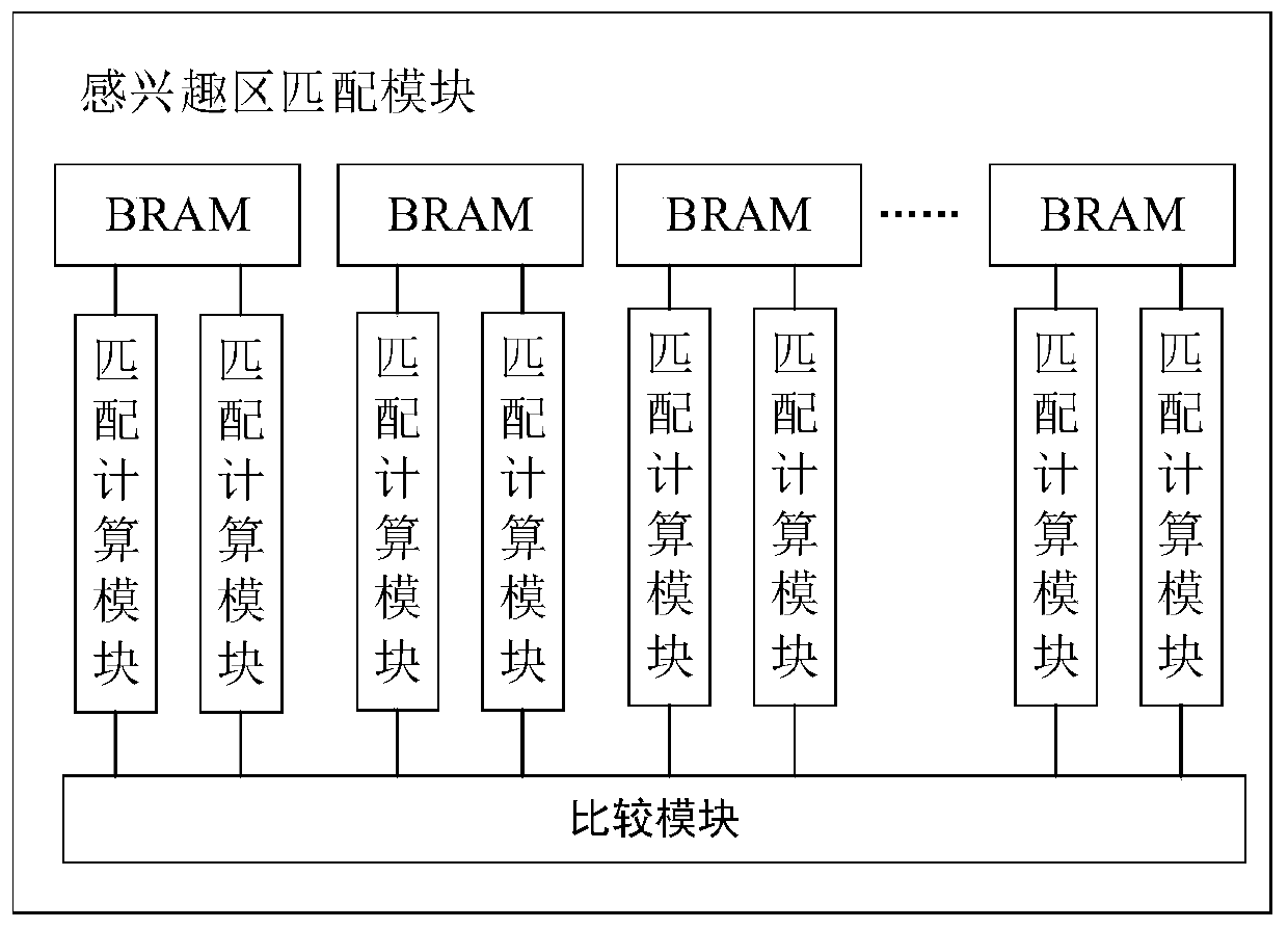
The invention discloses a template matching implementation device and method based on an FPGA. The device comprises a memory and the FPGA. The memory is used for storing an original image and selecting features to obtain a region-of-interest image; an ROM for storing template data and a plurality of region-of-interest matching modules are arranged in the FPGA; the region-of-interest images are respectively stored in the region-of-interest matching modules, each module is provided with a plurality of dual-port BRAMs, and each BRAM is respectively connected with the two matching calculation modules; all the matching calculation modules are connected with the comparison module; a single-frame region-of-interest image is divided into a plurality of sections which are respectively stored in theBRAM; and the matching calculation module is used for calculating the matching degree of the module and the corresponding section of region-of-interest image and outputting the matching metric valueof the single section of image, and the comparison module obtains the maximum/minimum value of the matching metric value in the multiple sections of images through calculation as the matching metric value of the single region-of-interest. According to the technical scheme, template matching is carried out in a parallel mode, and a result is rapidly obtained.
Description
technical field [0001] The invention relates to the field of image processing, in particular to an FPGA-based template matching implementation device and method. Background technique [0002] Template matching is the most basic and commonly used matching method in image processing. Template matching is a technique for finding the region most similar to a template image in an image, which can be used for object positioning and recognition. Due to the huge amount of calculations for template matching, it is mostly implemented in PCs or industrial computers, which has disadvantages such as high cost, large volume, and high power consumption, which limit the application scenarios of template matching. At the same time, when the template matching is performed on the existing embedded platform, the calculation time is long, and it is difficult to meet the real-time requirement. Contents of the invention [0003] In order to solve the above technical problems, the present inven...
Claims
Login to View More Application Information
Patent Timeline
 IPC IPC(8): G06K9/62G06K9/32
CPCG06V10/25G06V10/751G06F18/22Y02D10/00
Inventor 张方元吕猛张华东
Owner 易思维(杭州)科技有限公司
Features
- R&D
- Intellectual Property
- Life Sciences
- Materials
- Tech Scout
- Unparalleled Data Quality
- Higher Quality Content
- 60% Fewer Hallucinations
Learn More Browse by: Latest US Patents, China's latest patents, Technical Efficacy Thesaurus, Application Domain, Technology Topic, Popular Technical Reports.
© 2025 PatSnap. All rights reserved.Legal|Privacy policy|Modern Slavery Act Transparency Statement|Sitemap|About US| Contact US: help@patsnap.com