Wireless tag, wireless tag reader/writer, wireless tag information provision method, and wireless tag system

a technology of wireless tags and information provision methods, which is applied in the field of wireless tags, wireless tags, wireless tag information provision methods, and wireless tags. it can solve the problems of shortening the product life of wireless tags, affecting the use of storage areas, and wasting a large amount of time. the effect of shortening the communication tim

Active Publication Date: 2006-10-26
NEC CORP
View PDF10 Cites 35 Cited by
  • Summary
  • Abstract
  • Description
  • Claims
  • Application Information

AI Technical Summary

Benefits of technology

[0028] According to the present invention, a wireless tag having built-in sensors is provided with a determination unit so that the wireless tag is able determine whether sensor data is normal or not. The wireless tag is also able to store the sensor data. Since the wireless tag has the determination unit, there is no need of transmitting all the data from the wireless tag. This makes it possible to shorten the communication time and to ascertain the determination result quickly. Also, the wireless tag reader / writer is able to acquire only the data that has been determined to be normal or abnormal as a determination result without requesting all the detected information from the wireless tag. The detected information storage unit is able to store only the data that has been determined to be normal or abnormal, and thus the used storage area can be reduced.

Problems solved by technology

This induces a problem that it takes a long time to retrieve the data if the volume of the data detected by the sensors is large.
When a large volume of data has to be retrieved from a wireless tag having built-in sensors, in particular, a battery incorporated in the wireless tag is consumed quickly, which shortens the product life of the wireless tag.
This induces a problem that it takes a long time to read the data if a volume of the temperature history data is large.
Therefore, the system is unable to read or determine about data that varies all the time, for example, data of temperature around the wireless tag or temperature of the commodity to which the wireless tag is attached.
This induces a problem that it takes a long time to process data when the data is requested.

Method used


Image

  • Wireless tag, wireless tag reader/writer, wireless tag information provision method, and wireless tag system
  • Wireless tag, wireless tag reader/writer, wireless tag information provision method, and wireless tag system
  • Wireless tag, wireless tag reader/writer, wireless tag information provision method, and wireless tag system

Examples


first embodiment

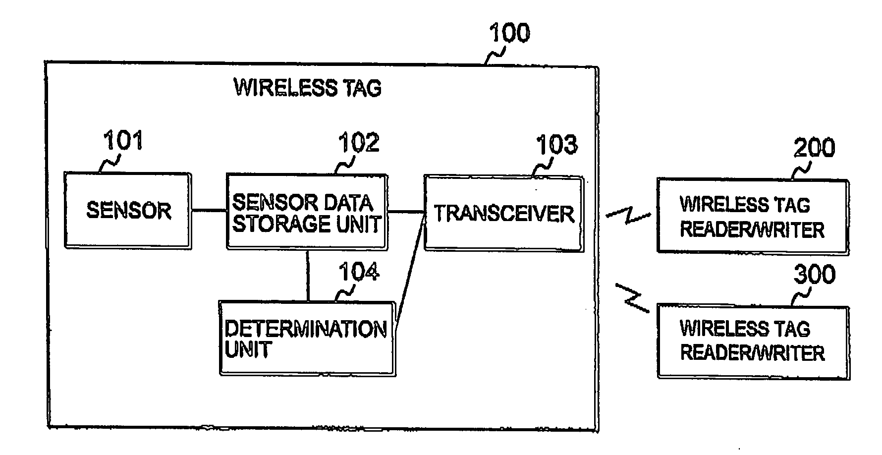
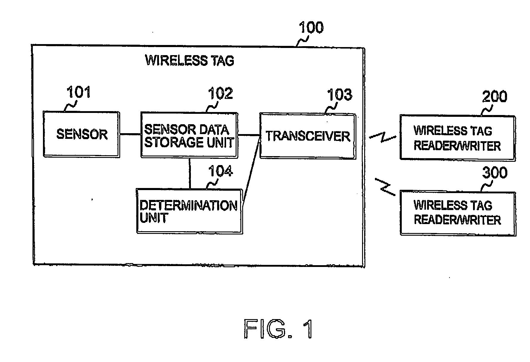
[0033] A first embodiment of the present invention will now be described with reference to the accompanying drawings. FIG. 1 is a block diagram illustrating a first embodiment of a wireless tag system according the present invention. The wireless tag system shown in FIG. 1 includes a wireless tag 100, a wireless tag reader / writer 200, and a wireless tag reader / writer 300.

[0034] The wireless tag 100 includes a sensor 101, a sensor data storage unit102, a transceiver 103, and a determination unit 104. The wireless tag 100 further includes a CPU (not shown) operating according to a program and a storage device (not shown) storing the program. Functions of the wireless tag 100 are carried out by the CPU executing the program designed to perform the functions.

[0035] The sensor 101 is for detecting a physical amount such as temperature or pressure, and detects such data relating to the area surrounding the wireless tag and a commodity to which the wireless tag is attached. The sensor da...

second embodiment

[0051] A second embodiment of the present invention will now be described with reference to the drawings. FIG. 3 is a block diagram illustrating a wireless tag system according to the second embodiment of the present invention. A wireless tag system shown in FIG. 3 includes a wireless tag 100, a wireless tag reader / writer 200, and a wireless tag reader / writer 300.

[0052] The wireless tag 100 includes a sensor 101, a sensor data storage unit 102, a transceiver 103, a determination unit 104, and a determination result storage unit 105. The wireless tag 100 further includes a CPU operating according to a program and a storage device storing the program. Functions of the wireless tag 100 are implemented by the CPU executing the program designed to perform the functions.

[0053] The determination result storage unit 105 is a storage area for storing a determination result output by the determination unit 104. In other aspects, the configuration of the wireless tag system is similar to tha...

third embodiment

[0062] The description of the embodiments above has been made in terms of an example in which the determination result output by the determination unit 104 is information indicating whether or not abnormal data is contained in the sensor data. However, the determination result may be information containing abnormal data or a time at which the abnormal data is detected. Further, the determination result may be information containing abnormal data and a time at which the abnormal data is detected.

[0063] A description will now be made of a third embodiment of the present invention relating to a case in which information of the determination result contains abnormal data and a time at which the abnormal data is detected. System configuration of the third embodiment is similar to that of the first embodiment (see FIG. 1) and hence the description thereof will be omitted.

[0064] The sensor 101 stores detected data and detected time thereof in association with each other in the sensor dat...


PUM


Abstract

A system comprising a wireless tag and a tag reader. The tag comprises: a sensor for generating a detected information; a storage for storing the detected information; a determination unit for storing a criteria information and outputting a result of determination on the detected information on the basis of the criteria information; and a communication control unit for transmitting the determination result in response to receiving a request. The reader transmits the request to the tag and receives the determination result from the tag.

Description

[0001] This application claims priority to prior Japanese patent application JP 2005-126277, the disclosure of which is incorporated herein by reference. BACKGROUND OF THE INVENTION [0002] 1. Field of the Invention [0003] The present invention relates to a wireless tag capable of acquiring information detected by a built-in sensor, a wireless tag reader / writer, a wireless tag information provision method, and a wireless tag system. [0004] 2. Description of the Related Art [0005] Along with development of information communication technology, the trend has set in to perform commodity management or to streamline the commodity information display or the commodity distribution by packaging a Radio Frequency (RF) tag having an integrated circuit with memory [generally, sometimes called as electronic tag, contactless data carrier, wireless IC tag, contactless IC, contactless IC label, contactless IC tag, RFID (Radio Frequency Identification) or NFC (Near Field Communication) tag] in artic...

Claims


Application Information

Patent Timeline
Patent Type & Authority Applications(United States)
IPC IPC(8): H04Q5/22
CPCG06K19/0723G06K19/0716
Inventor TAKATAMA, HIROKAZU
Owner NEC CORP
Why Eureka
Try Eureka