Projectile diverter

a technology of projectiles and diverters, which is applied in direction controllers, instruments, weapons, etc., can solve the problems of ineffective force over a long time period, difficult for a rocket motor with loose loaded propellant to burn all of its propellant, and ineffective when a relatively high impulse, etc., to achieve fast functioning diverter results, low cost, and compact high impulse

Inactive Publication Date: 2006-02-28
QUANTIC INDS
View PDF25 Cites 35 Cited by
  • Summary
  • Abstract
  • Description
  • Claims
  • Application Information

AI Technical Summary

Benefits of technology

[0008]One advantage of the present invention is a relatively low cost, high impulse compact, and fast functioning diverter results compared to what can be provided with a small rocket motor. The use of the reactive semiconductor bridge allows very fast firings since ignition occurs in microseconds. The reactive semiconductor bridge allows reliable operation at low input energies since the reactive semiconductor bridge provides a large energy output to ignite the prime. The reactive semiconductor bridge can ignite prime across a gap and this provides a safety margin in case the shock or acceleration of projectile launch would cause the prime to become separated from the bridge. Reliable diverters can be therefore built at relatively low cost using this technology.
[0009]Thus, in one embodiment, the invention relates to a small fast diverter for use with a projectile for steering the projectile in flight by ejecting an end cap of the diverter in response to a signal from a guidance system. In another embodiment, the invention relates to a diverter and other impulse type of cartridges capable of high impulse, such as less than 1 ms, without throwing a mass such as the end cap, but instead using the ejection of the hot high-pressure velocity gases out of the diverter body.

Problems solved by technology

Providing the force over this time period is not efficient.
One might consider using small rocket motors for diverters having small volume, but this has proven ineffective when a relatively high impulse is required over a short time.
It is too difficult for a rocket motor with loose loaded propellant to burn all of its propellant in a short time without ejecting a large percentage of the propellant unburned.
Further, the relatively low packing density of propellant results in the rocket motor ejecting a considerable volume of propellant.
Additionally, the rocket propellant container cannot be manufactured that small.
Providing the propellant in a higher density form, e.g., cast propellant grain, might appear helpful, but a compact single grain is unlikely to have a thin enough web to operate in the required time period due to propellant burn rate limitations.
Where low cost is required, such as less than $5.00 per diverter, without large capital investment, it is difficult to envision good results with rocket motors.
Additionally, rocket motors are not volume efficient for another reason.
Another approach might be to use conventional bridgewire pyrotechnic devices for small diverters, but there are unsolved problems.
One problem is how to ignite them quickly and reliably.
Conventional semiconductor bridge technology provides very fast hot ignition, but it is also only low energy ignition lasting for microseconds.
The energy output is dependent on energy input; when only low input energy is available, only small output energy can be produced, which may not be sufficient to provide reliable ignition.
Further, conventional pyrotechnic devices and semiconductor bridges require tight coupling between the ignition element and the pyrotechnic material.
This means lower ignition energy can be used, but it requires intimate contact between the bridge and prime, adding to manufacturing costs.
During such events the prime may separate from the ignition element and reduce the reliability of the diverter.
Bridgewires require high firing energies or very small and unsafe bridgewires for fast response.
Thus, attempts to produce small low cost diverters generating relatively high impulse over brief periods of time have not been successful.

Method used


Image

  • Projectile diverter
  • Projectile diverter
  • Projectile diverter

Examples


Embodiment Construction

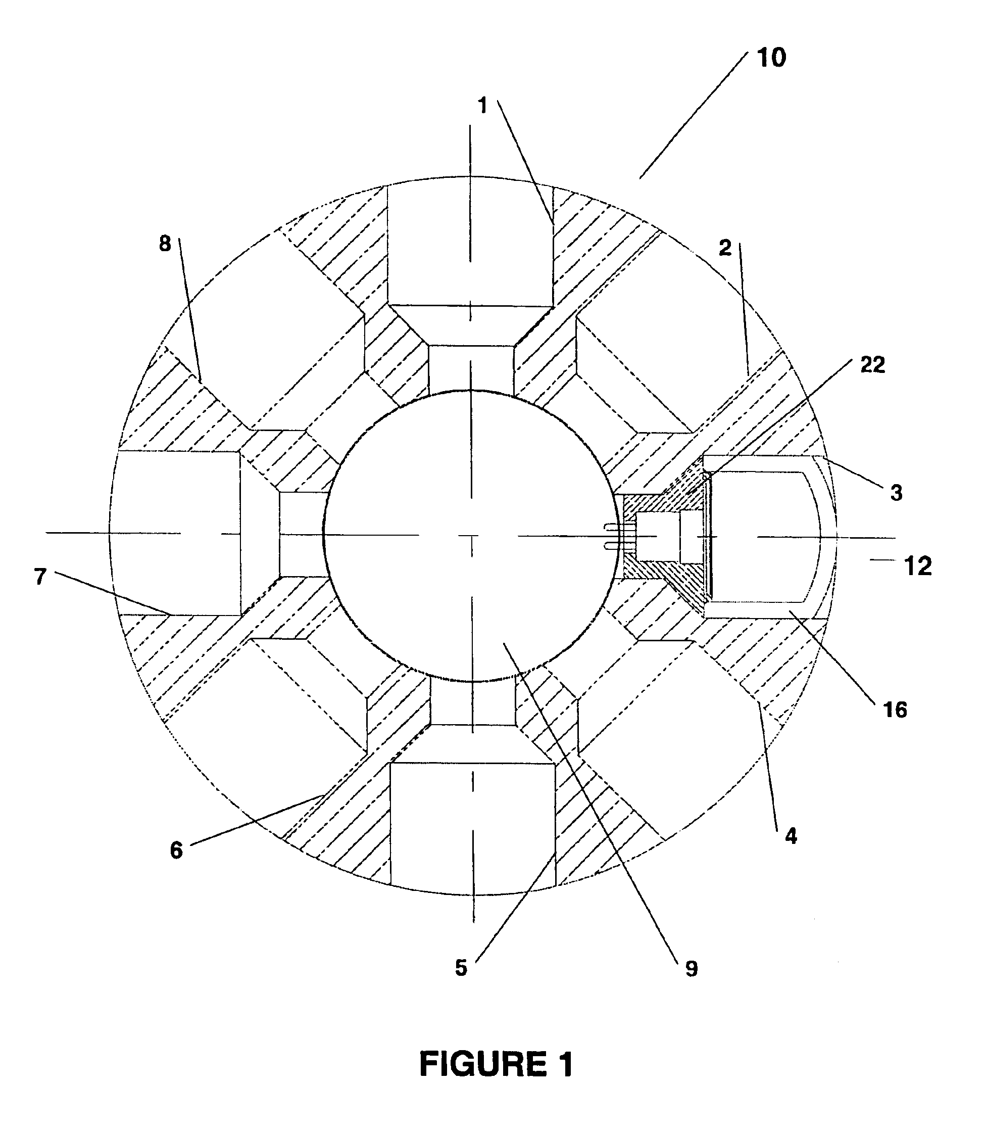
[0020]FIG. 1 shows a cross-sectional view of a rocket 10 with a single diverter 12 on the right side. In this embodiment, the rocket 10 is a 2.75-inch diameter rocket. It should be apparent from the specification, however, that the diverter would be useful on many types of projectiles. As shown in FIG. 1, the core of rocket 10 has eight barrels 1, 2, 3, 4, 5, 6, 7, and 8 for installing eight diverters, just like diverter 12, in a band about the rocket 10. The rocket 10 includes a free passage 9 to allow connection of each of the diverters 12 to the fireset (not shown).

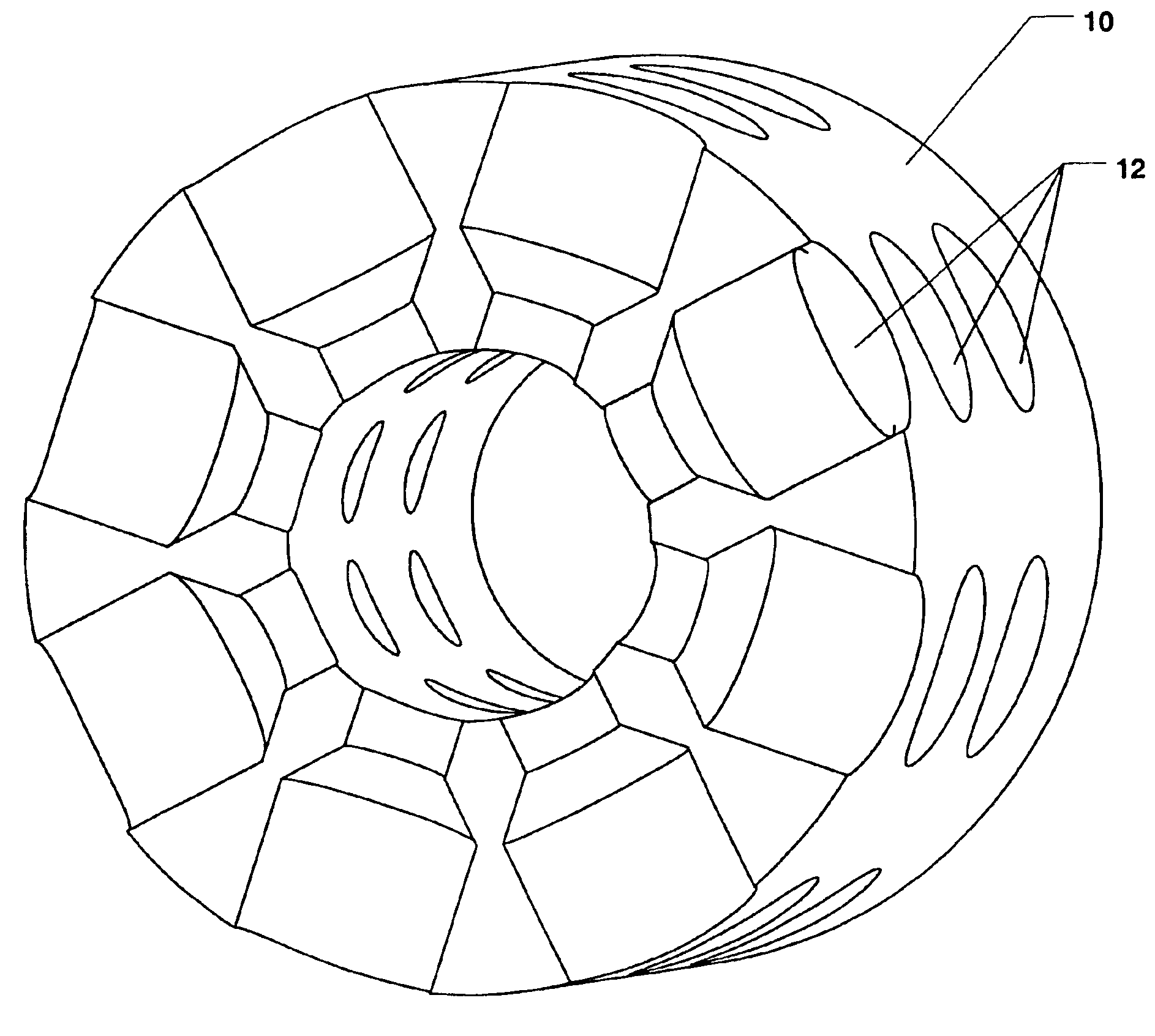
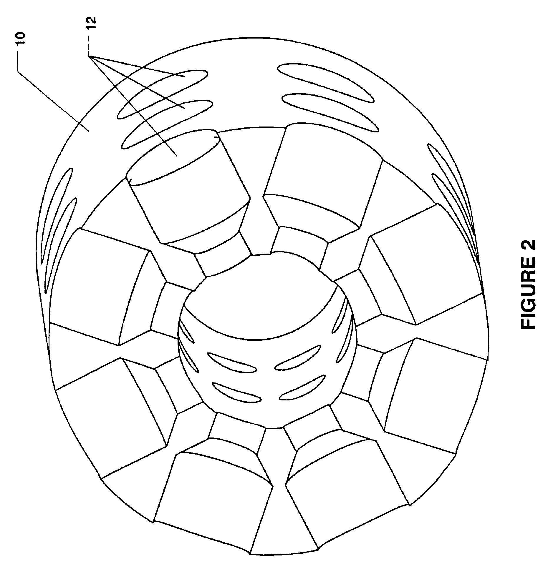
[0021]The diverters can be arranged in several bands about the rocket 10 as shown in FIG. 2. FIG. 2 illustrates a perspective view of the rocket 10 with three bands of diverters 12. Each band includes eight diverters, but other amounts are possible besides those shown in FIGS. 1-2. FIG. 2 shows a partial cross-section through the first of three bands of diverters.

[0022]As shown in FIGS. 1-2, the diverters have axes per...


PUM


Abstract

The present invention provides a fast, low-cost, small diverter capable of generating a relatively high impulse (1-5 N-sec) over a short time period. The diverter is adapted for installation in a projectile for steering the projectile in flight by ejecting an end cap or hot burning gases in response to control signals from a guidance system. In one embodiment, multiple diverters are arranged in one or more bands about a flying projectile such as a rocket. Each diverter includes a header assembly providing support for a plurality of electrical leads, a mounting surface either on the header assembly or on a sealing assembly, a reactive semiconductor bridge mounted on the mounting surface and providing an electrical path for the electrical leads at a certain voltage across the bridge, a diverter body supporting the header assembly and containing a prime, wherein the reactive semiconductor bridge and the prime permit a gap, and an end cap or a sealing assembly attached to the diverter body containing the propellant.

Description

[0001]This application is a continuation of U.S. application No. 09 / 782,198, filed on Feb. 8, 2001, now abandoned, which is a continuation-in-part of U.S. application No. 09 / 502,119, now U.S. Pat. No. 6,367,735 B1, filed on Feb. 10, 2000, which are hereby incorporated by reference. The present invention relates to controlling the flight path of rockets, missiles, and other flying projectiles. In particular, the invention relates to a small fast diverter for use with a projectile for steering the projectile in flight.BACKGROUND OF THE INVENTION[0002]In general, a diverter generates lateral reaction force to steer a rocket, missile, and other projectile in flight. The amount of impulse generated by the diverter will determine how much the flight path is diverted. Impulse is the product of the average reaction force over the time exerted.[0003]Recent applications for diverters include steering 2.75-inch diameter rockets, artillery, and gun projectiles, e.g., 30 mm projectiles. In such ...

Claims


Application Information

Patent Timeline
Patent Type & Authority Patents(United States)
IPC IPC(8): F41G7/00F41G7/30F42B3/13
CPCF41G7/305F42B10/661F42B3/13
Inventor FOLSOM, MARKPIPER, III, CHARLESFAHEY, WM. DAVIDMCGOWAN, JARED M.
Owner QUANTIC INDS
Why Eureka
Try Eureka