
Cooking utensil

A technology for cooking utensils and pressure relief, applied to cooking utensils, household utensils, kitchen utensils, etc., can solve problems such as complicated operation steps, danger, product damage, etc., achieve convenient and quick operation, eliminate safety hazards, and improve use safety Effect

Active Publication Date: 2020-02-21
FOSHAN SHUNDE MIDEA ELECTRICAL HEATING APPLIANCES MFG CO LTD
View PDF10 Cites 0 Cited by
  • Summary
  • Abstract
  • Description
  • Claims
  • Application Information

AI Technical Summary

Problems solved by technology

In the existing electric rice cooker, because there is negative pressure in the pot, when the lid needs to be opened, it must be unlocked first by vacuum (unlocking by pushing a small ball through an electromagnet), and then pressing the button to open the lid. Not only the operation steps are complicated, but also the user The lid cannot be opened only by pressing the lid opening button, which may easily make consumers think that the product is damaged, and then make repairs or complaints
In addition, when the electromagnet is damaged, the product has been stored in a negative pressure state, which is very dangerous

Method used


Image

  • Cooking utensil
  • Cooking utensil
  • Cooking utensil

Examples


no. 1 example

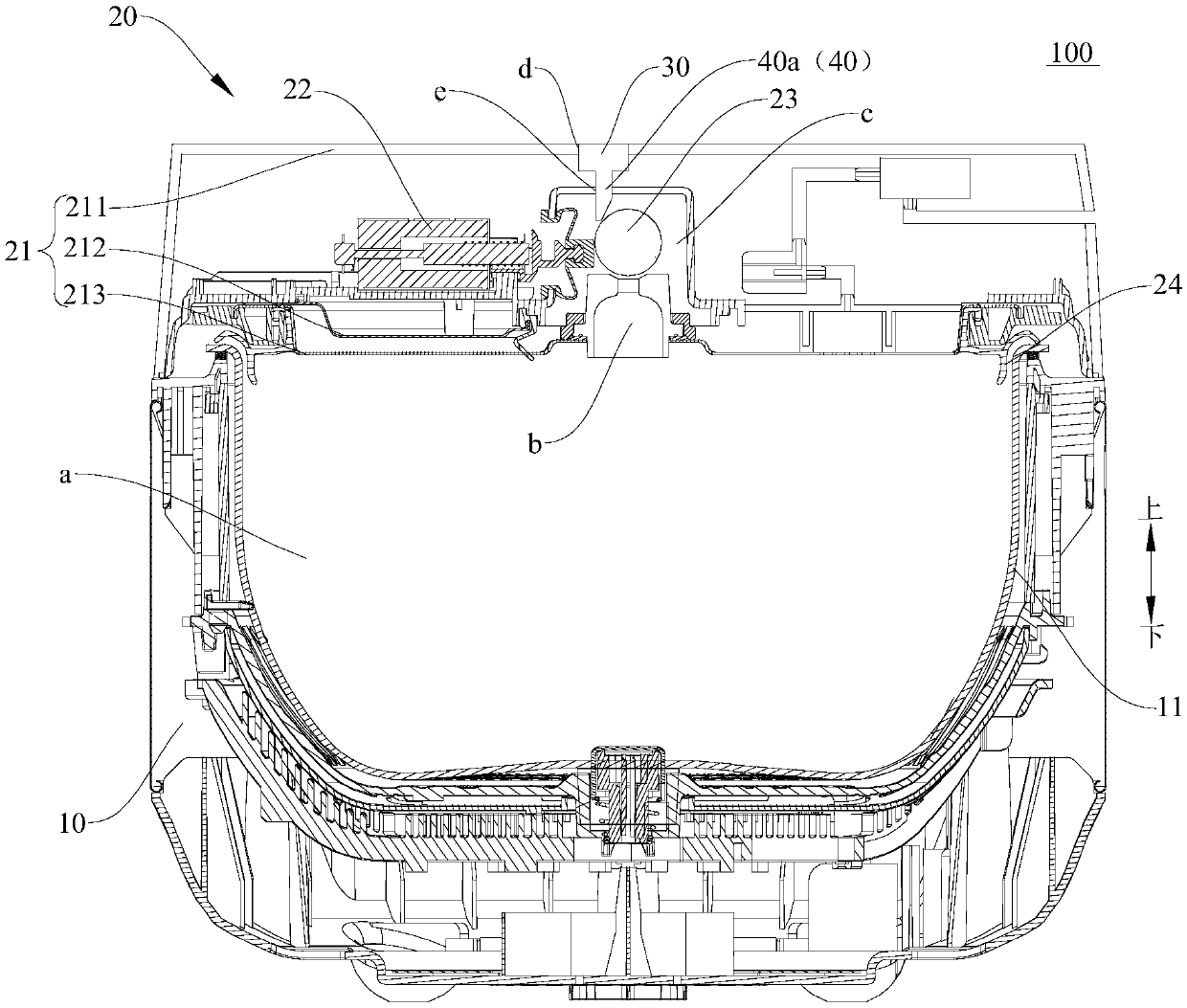
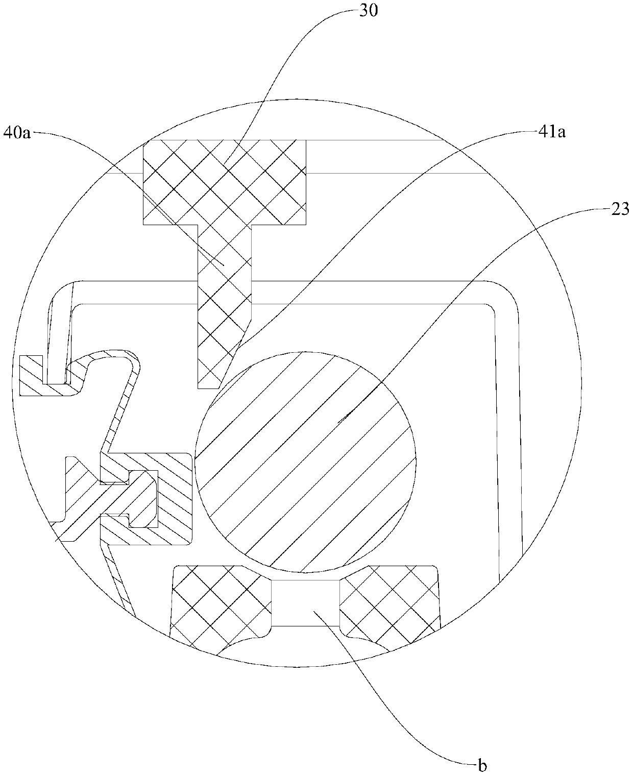
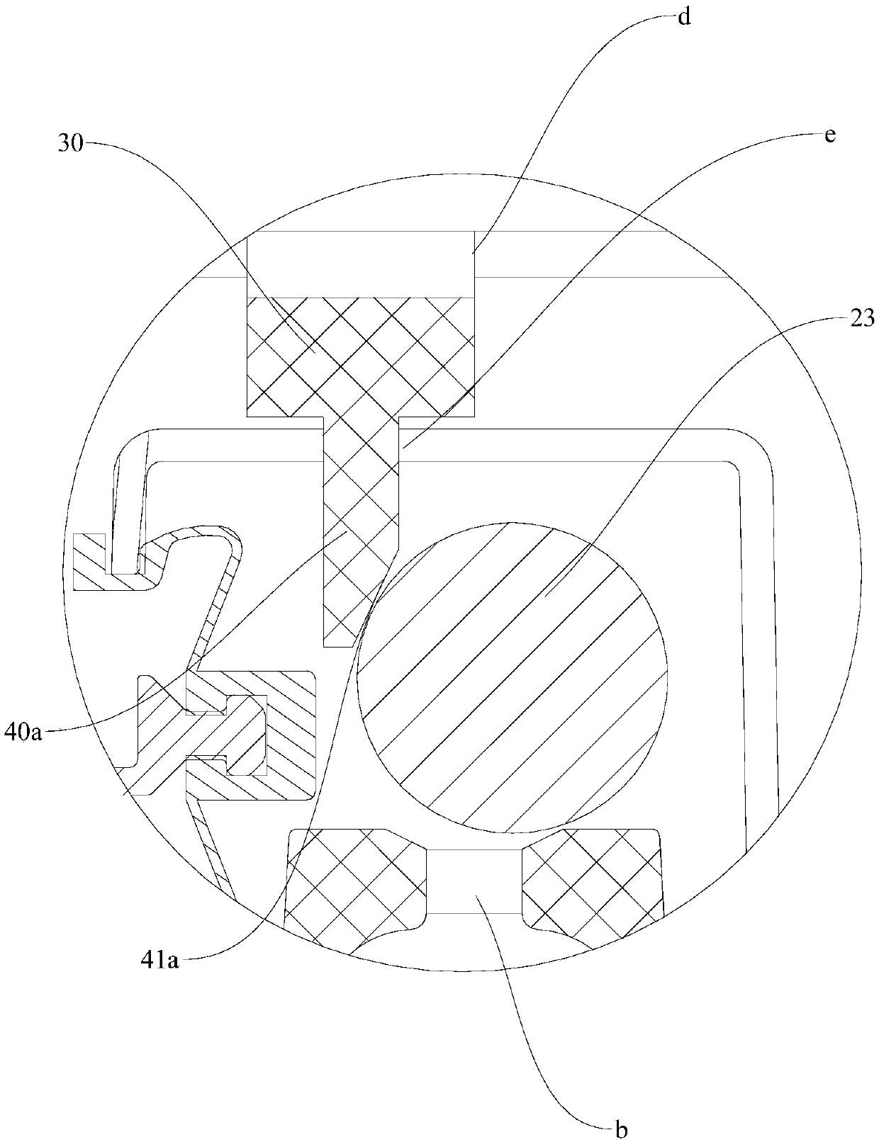
[0047] Such as figure 2 and image 3 As shown, the mechanical pressure relief member 40 is configured to drive the first sealing member 23 to open the pressure relief hole b when the cover opening button 30 is pressed, and the cover opening button 30 and the mechanical pressure relief member 40 are both arranged on the upper cover body 21 . That is to say, in the first embodiment, the mechanical pressure relief member 40 realizes the pressure relief of the cooking cavity a by controlling whether the pressure relief hole b is opened or not.

[0048] Such as figure 1 , figure 2 and image 3 As shown, the first sealing member 23 is a sealing ball, the mechanical pressure relief member 40 is a pressure relief push rod 40a, and the pressure relief push rod 40a and the cover opening button 30 are slidably arranged in a direction parallel to the central axis of the pressure relief hole b. On the upper cover body 21, the pressure relief push rod 40a has an inclined push surface...

no. 2 example

[0055] Such as Figure 4 As shown, the mechanical pressure relief member 40 is configured to: drive the first sealing member 23 to open the pressure relief hole b when the uncap button 30 is pressed, the uncap button 30 is arranged on the pot body 10 and the mechanical pressure relief member 40 is located on the Cover 20 on the pot. That is to say, in the second embodiment, the mechanical pressure release member 40 is driven by the uncap button 30 positioned on the pot cover 20, so that the pressure release hole b is opened to complete the pressure release.

[0056] exist Figure 4 In the specific embodiment shown, the mechanical pressure relief member 40 is a pressure relief link 40b, an extension rod 60 is provided on the upper end of the cover opening button 30, and the extension rod 60 protrudes from the upper end of the pot body 10 and extends into the pot cover 20 The inside is suitable for driving the pressure relief link 40b located in the pot cover 20 .

[0057] Sp...

no. 3 example

[0066] Such as Figure 5 , Figure 6 and Figure 7 As shown, the pot cover 20 has a second sealing member 24, and the second sealing member 24 is suitable for fitting with the inner pot 11 to seal the cooking cavity a when the pot cover 20 is closed, and the mechanical pressure relief member 40 is configured to: when the cover is opened When the button 30 is pressed, it acts on the second seal 24 to release the seal between the pot cover 20 and the inner pot 11 . That is to say, in the third embodiment, the mechanical pressure relief member 40 acts on the second sealing member 24 to directly realize the pressure relief of the cooking cavity a.

[0067] Such as Figure 6 and Figure 7 As shown, the second sealing member 24 is a sealing ring connected to the lower end of the upper cover body 21, and the mechanical pressure relief member 40 has a prying claw 40c, and the prying claw 40c is inserted into the second sealing member when the cover opening button 30 is pressed. 2...


PUM


Abstract

The invention discloses a cooking utensil. The cooking utensil comprises a pot body, a pot cover, a cover opening button and a mechanical pressure relief part, wherein the pot body is provided with aninner pot, and a cooking cavity is defined in the inner pot; the pot cover is arranged on the pot body in an openable and closable mode, the pot cover comprises an upper cover body, an electric pressure relief part and a first sealing part, the upper cover body is provided with a pressure relief hole and a pressure relief cavity which are arranged opposite to the cooking cavity, and the electricpressure relief part is configured to be capable of being electrically controlled to drive the first sealing part to open or close the pressure relief hole; the cover opening button is arranged on thepot body or the pot cover; and the mechanical pressure relief part is connected or linked with the cover opening button, and the mechanical pressure relief part is configured to drive the first sealing part to open the pressure relief hole and / or release sealing between the pot cover and the inner pot when the cover opening button is pressed. Therefore, the cooking utensil has the functions of electric control pressure relief and manual pressure relief having no interferencewitheach other, pressure can be relieved and the cover body can be opened while the cover opening button is pressed down, the operation is convenient and fast, and the reliability and safety are better.

Description

technical field [0001] The present invention relates to the technical field of cooking utensils, in particular to a cooking utensil. Background technique [0002] In the related art, an electric rice cooker with a vacuum function generally needs to release the pressure after the pressure maintaining is completed to restore the pressure in the cooking chamber to normal, so that the lid of the cooking utensil can be opened safely after the pressure release is completed. In the existing electric rice cooker, because there is negative pressure in the pot, when the lid needs to be opened, it must be unlocked first by vacuum (unlocking by pushing a small ball through an electromagnet), and then pressing the button to open the lid. Not only the operation steps are complicated, but also the user The pot lid cannot be opened only by pressing the lid opening button, which may easily make consumers think that the product is damaged, and then make repairs or complaints. In addition, wh...

Claims


Application Information

Patent Timeline
Patent Type & Authority Applications(China)
IPC IPC(8): A47J27/08
CPCA47J27/0802
Inventor 刘化勇罗飞龙梁志佳黄韦铭邢胜华羊小亮
Owner FOSHAN SHUNDE MIDEA ELECTRICAL HEATING APPLIANCES MFG CO LTD
Learn More