Backlight module, display screen and terminal

A backlight module and light guide plate technology, which is applied in optics, nonlinear optics, printing devices, etc., can solve problems such as the camera area cannot be displayed, the terminal screen ratio is limited, and the terminal display effect is affected.

Active Publication Date: 2020-02-28
SHENZHEN TECHASER TECH
View PDF16 Cites 11 Cited by
  • Summary
  • Abstract
  • Description
  • Claims
  • Application Information

AI Technical Summary

Problems solved by technology

[0003] The backlight module, display screen, and terminal provided by the embodiments of the present invention mainly solve the technical problem that the area corresponding to the camera under the screen cannot be displayed in the display screen, which limits the proportion of the terminal screen and affects the display effect of the terminal.

Method used


Image

  • Backlight module, display screen and terminal
  • Backlight module, display screen and terminal
  • Backlight module, display screen and terminal

Examples


Embodiment 1

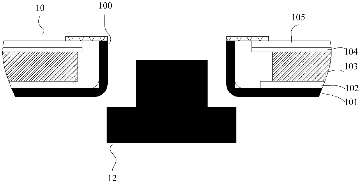
[0038] figure 1 It shows a schematic diagram of setting up an under-display camera. figure 1 Among them, the backlight module 10 is provided with a through hole 100, and the through hole 100 penetrates the outer frame 101 of the backlight module 10: the bottom wall of the outer frame 101 is provided with an upwardly protruding protrusion, and the through hole 100 penetrates through the outer frame 101 of the backlight module 10. The upper surface of the raised portion and the bottom of the outer frame 101 . The outer frame 101 also includes a side wall, and the side wall and the bottom wall form a semi-enclosed accommodation chamber, which accommodates the reflective film 102 of the backlight module 10, the light guide plate 103, and the diffusion sheet 104 sequentially from bottom to top. , Brightening film 105 . In this embodiment, the reflective film 102, the light guide plate 103, the diffusion sheet 104, and the brightness enhancement film 105 are all provided with open...

example 1

[0052] For some examples of this embodiment, see Figure 3a The schematic cross-sectional view of the backlight module shown: the backlight module 30a includes a main backlight module 31 and a sub-backlight module 32, the main backlight module includes an outer frame 311, and the bottom wall of the outer frame 311 protrudes upwards to form a raised portion, the convex There is a through hole 300 in the rising part that runs through the upper surface of the raised part and the lower surface of the bottom wall of the outer frame. The main backlight module 31 also includes a reflective film, a main LED light source, a main light plate, and a diffusion sheet arranged on the bottom wall of the outer frame. and glossy film. The main backlight module 31 is a side-lit backlight module, so the LED chip in the main LED light source has a light-emitting side, and its light-emitting side is just facing the light-incoming side of the main light plate. In this embodiment, the top of the ra...

example 2

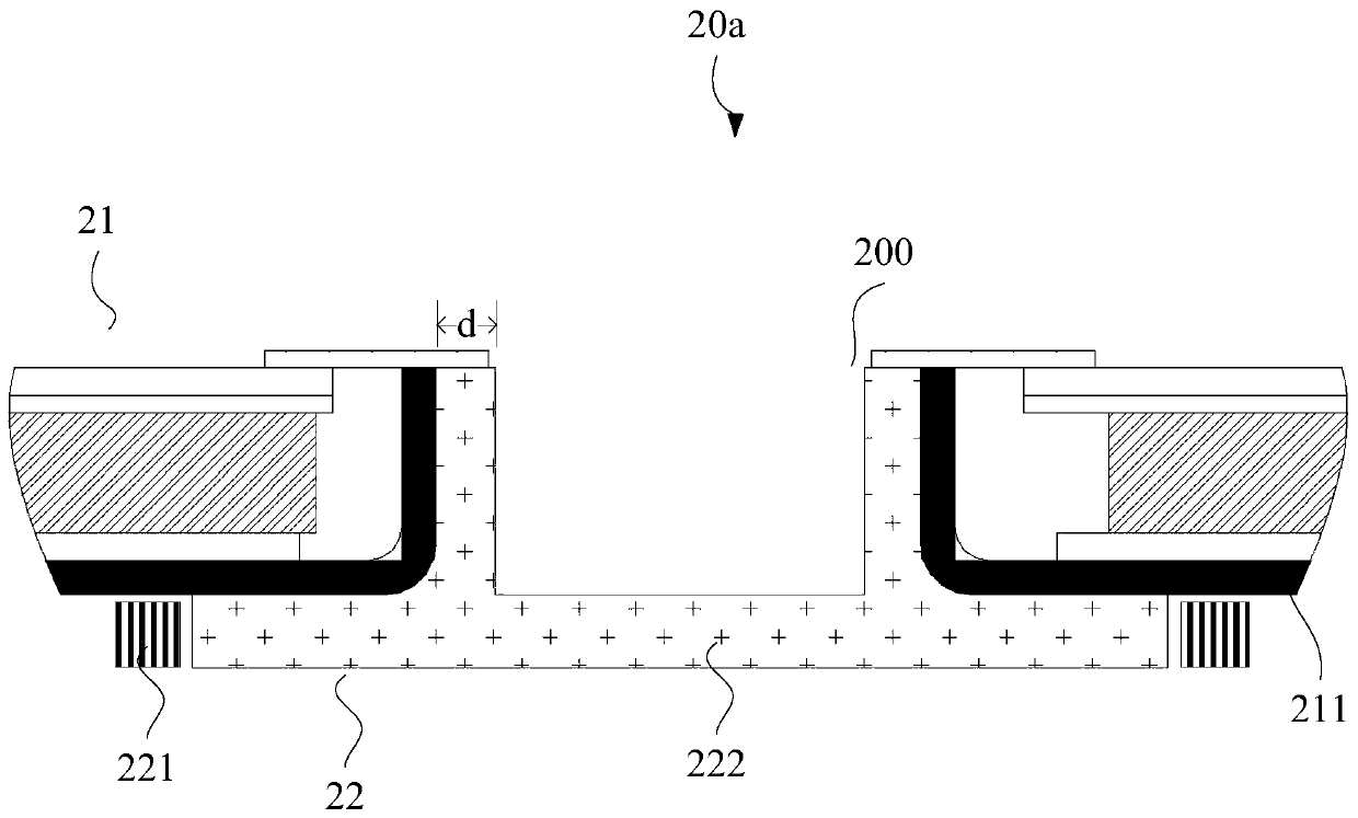
[0063] please continue to combine Figure 2a , in this example, the light exit part of the auxiliary backlight module 22 protrudes into the through hole 200, and the upper surface is recessed downwards to form a downwardly recessed groove, which is referred to as a "lower groove" here. . It should be noted that although the light exit portion of the secondary light guide plate 222 is recessed downward through the lower groove, the depression of the light exit portion does not reach the bottom surface of the secondary light guide plate 222, that is, the lower groove is not a groove that runs through the secondary light guide plate 222 . In some examples of this embodiment, the thickness of the groove bottom of the lower groove is equal to the thickness of the light entrance part of the sub-light guide plate 222, for example Figure 2a shown.

[0064] In some examples of this embodiment, the top of the side wall of the lower groove is flush with the top of the raised portion ...


PUM

PropertyMeasurementUnit
thicknessaaaaaaaaaa

Abstract

The embodiment of the invention provides a backlight module, a display screen and a terminal. A through hole is formed in an outer frame of a main backlight module, and a camera shooting hole is formed in an auxiliary LED light source below the through hole, so that an under-screen camera located below the auxiliary backlight module can perform image acquisition through the two holes. Meanwhile, alight emitting part of an auxiliary light guide plate extends into the through hole, and the vertical orthographic projection area of the auxiliary light guide plate covers the vertical orthographicprojection area of the through hole, so after the light emitted by the auxiliary LED light source enters the auxiliary light guide plate, the light can be emitted from the light emitting part in the through hole and the whole area of the upper surface of the through hole is lightened, so that the area, corresponding to the under-screen camera, in the backlight module can also be lightened, and a basis is provided for the display of the area of the display screen. Based on the backlight module provided by the embodiment of the invention, the screen-to-body ratio of the terminal is improved by the display screen, so a full screen is realized on the basis of an under-screen camera, and the improvement of the user experience of the terminal is facilitated.

Description

technical field [0001] The invention relates to the display field, in particular to a backlight module, a display screen and a terminal. Background technique [0002] In the process of constantly pursuing the large screen-to-body ratio of the terminal, people put forward the concept of "full screen". The full screen means that there is no longer a special space on the front of the terminal for setting the front camera, earpiece and other devices. Therefore, the "under-screen camera" came into being. The so-called under-screen camera refers to setting the front camera under the screen. The area corresponding to the camera cannot be illuminated for display, so a true full screen cannot be realized, which seriously affects the user experience. Contents of the invention [0003] The backlight module, display screen, and terminal provided by the embodiments of the present invention mainly solve the technical problem that the area corresponding to the under-screen camera in th...

Claims


Application Information

Patent Timeline
Patent Type & Authority Applications(China)
IPC IPC(8): G02F1/13357G03B29/00G03B30/00
CPCG02F1/133615G03B29/00
Inventor 姜必武古远琴
Owner SHENZHEN TECHASER TECH
Why Eureka
Try Eureka