Target position threshold determination method, apparatus and device, and storage medium

A technology of target position and determination method, which is applied in the field of image processing, can solve problems such as poor threshold accuracy, and achieve the effect of accurate threshold

Active Publication Date: 2020-02-28
安徽文香科技股份有限公司
View PDF4 Cites 3 Cited by
  • Summary
  • Abstract
  • Description
  • Claims
  • Application Information

AI Technical Summary

Problems solved by technology

[0006] In view of this, an embodiment of the present invention provides a method, device, device, and storage medium for determining a threshold of a target position, so as to solve the problem of poor accuracy of the threshold obtained in the prior art

Method used


Image

  • Target position threshold determination method, apparatus and device, and storage medium
  • Target position threshold determination method, apparatus and device, and storage medium
  • Target position threshold determination method, apparatus and device, and storage medium

Examples


Embodiment 1

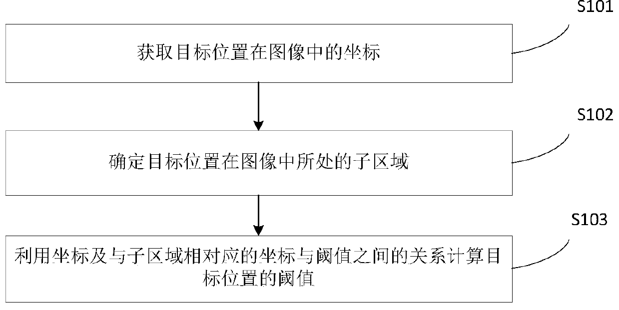
[0058] Embodiment 1 of the present invention provides a method for determining a threshold of a target position. figure 1 It is a schematic flow chart of the method for determining the target position threshold in Embodiment 1 of the present invention, as figure 1 As shown, the target position threshold determination method in Embodiment 1 of the present invention includes the following steps:

[0059] S101: Obtain the coordinates of the target position in the image.

[0060] S102: Determine the sub-region where the target position is located in the image.

[0061] Further, before determining the sub-area where the target position is located in the image, it also includes: selecting a position point in the image; when the number of the selected position points is an odd number, the position point is used as the vertex to form a sub-area; when selecting When the number of position points is an even number, use the position points as vertices to form a sub-region; or use the s...

Embodiment 2

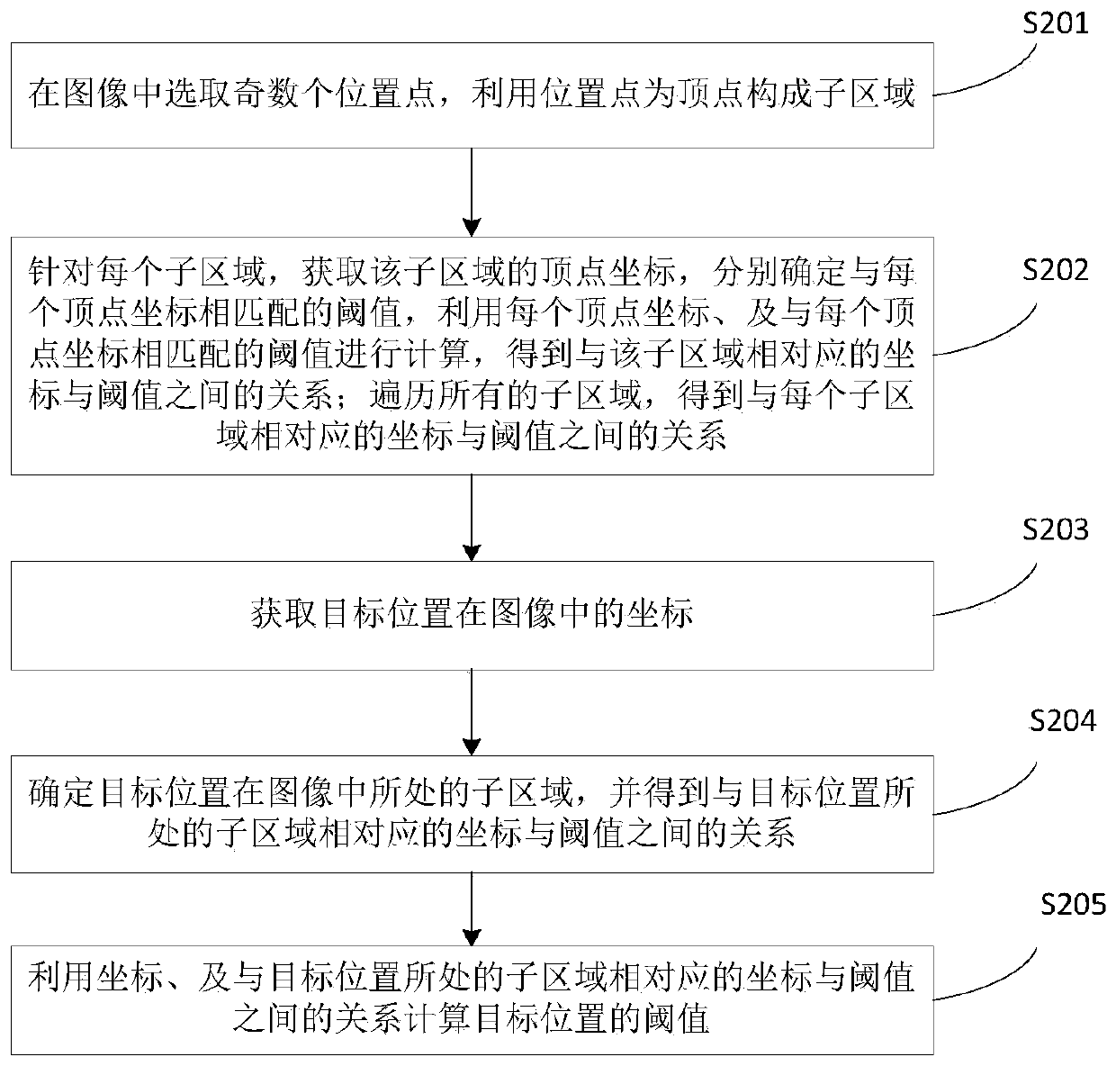
[0068] Embodiment 2 of the present invention provides a method for determining a threshold of a target position. figure 2 It is a schematic flow chart of the method for determining the target position threshold in Embodiment 2 of the present invention, as figure 2 As shown, the target position threshold determination method in Embodiment 2 of the present invention includes the following steps:

[0069] S201: Select an odd number of position points in the image, and use the position points as vertices to form sub-regions.

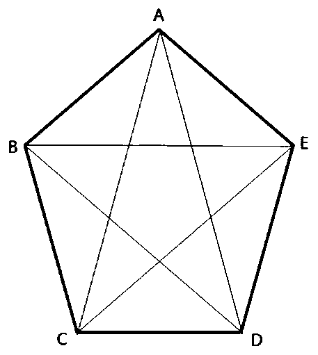
[0070] As a specific implementation manner, the number of selected points is 5. image 3 It is a schematic diagram of each sub-region of a specific example in Embodiment 2 of the present invention, such as image 3 As shown, five points A, B, C, D, and E are selected in the image, and the above five points divide the image into 10 sub-regions.

[0071] S202: For each sub-area, obtain the vertex coordinates of the sub-area, respectively determine the thr...

Embodiment 3

[0081] Embodiment 3 of the present invention provides a method for determining a threshold of a target position. Figure 7 It is a schematic flow chart of the method for determining the target position threshold in Embodiment 3 of the present invention, as Figure 7 As shown, the target position threshold determination method in Embodiment 3 of the present invention includes the following steps:

[0082] S701: Select an even number of position points in the image, use the selected position points as vertices to form a polygon, obtain midpoints of each side of the polygon respectively, and use the selected position points and midpoints as vertices to form subregions.

[0083] As a specific implementation manner, the number of selected points is 4. Figure 8 It is a schematic diagram of each sub-region of a specific example in Embodiment 3 of the present invention, such as Figure 8 As shown, five points A, B, C, and D are selected in the image, and the above five points divid...


PUM


Abstract

The invention discloses a target position threshold determination method, apparatus and device, and a storage medium. The target position threshold determination method comprises the following steps:obtaining coordinates of a target position in an image; determining a sub-region where the target position is located in the image; and calculating a threshold value of the target position by utilizing the coordinates and a relationship between the coordinates corresponding to the sub-regions and the threshold value. According to the technical scheme, the threshold value of the target position iscalculated through the relation between the coordinate of the relatively small area and the threshold value, so that the calculated threshold value is more accurate and closer to a nonlinear optimal solution.

Description

technical field [0001] The present invention relates to the technical field of image processing, in particular to a method, device, equipment and storage medium for determining a threshold of a target position. Background technique [0002] In the image tracking and positioning algorithm, a judgment threshold is often set for the corresponding position in the image. Certain thresholds are usually not global thresholds, but relative to image coordinates. For example, when the image is an image captured by a camera overlooking a certain space, the threshold value is the threshold value of the pixel area (the number of pixels belonging to the target) to determine whether a certain moving target is valid. Then this threshold will be affected by the principle of perspective. The farther away from the camera in the image, the smaller the target pixel area, and the closer the pixel area is, the larger. [0003] For another example, if an object with an area larger than 100 pixels...

Claims


Application Information

Patent Timeline
Patent Type & Authority Applications(China)
IPC IPC(8): G06T7/70G06T7/11G06T7/136
CPCG06T7/11G06T7/136G06T7/70
Inventor 张轶君朱玉荣彭泽波
Owner 安徽文香科技股份有限公司
Why Eureka
Try Eureka