Supercharge Your Innovation With Domain-Expert AI Agents!

Optical system, projection device and head mounted device

A technology for optical systems and optical components, applied in optics, optical components, instruments, etc., to solve problems such as the inability to meet the requirements of large fields of view of optical systems

Active Publication Date: 2022-04-22
GOERTEK OPTICAL TECH CO LTD
View PDF0 Cites 0 Cited by
  • Summary
  • Abstract
  • Description
  • Claims
  • Application Information

AI Technical Summary

Problems solved by technology

[0003] The present invention provides an optical system, a projection device and a head-mounted device, aiming to solve the problem that the optical system cannot meet the requirement of a large field of view when the optical system uses a small-sized display chip in the prior art

Method used


Image

  • Optical system, projection device and head mounted device
  • Optical system, projection device and head mounted device
  • Optical system, projection device and head mounted device

Examples


no. 1 example

[0054] In the first embodiment, the optical system design data are shown in Table 1 below:

[0055] Table 1

[0056]

[0057]

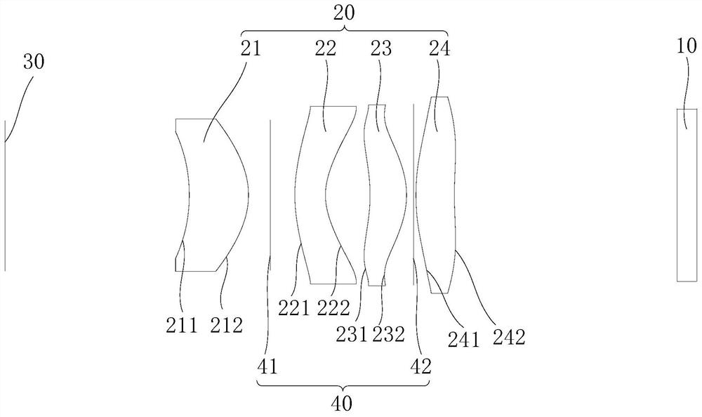
[0058] Wherein, the first surface 211 to the eighth surface 242 are aspherical structures, where α 1 、α 2 、α 3 、α 4 、α 5 、α 6 is the aspheric high-order term coefficient of the aspheric lens, as shown in Table 2 for details.

[0059] Table 2

[0060]

[0061]

[0062] In the first embodiment, each parameter is as follows:

[0063] The lens total length (Total Track Length, TTL) of described lens group 20 is 23.952mm;

[0064] The focal length (Effective Focal Length, EFL) of the lens group 20 is 8.232mm;

[0065] The field of view (Field of View, FOV) of the optical system is 40°;

[0066] The image height of the mirror group 20 is 6.058mm;

[0067] The focal length of the first lens 21 is 7.981mm;

[0068] The focal length of the second lens 22 is -6.564mm;

[0069] The focal length of the third lens 23 is 8.399mm;

[0070] ...

no. 2 example

[0074] In the second embodiment, the optical system design data are shown in Table 3 below:

[0075] table 3

[0076]

[0077]

[0078] Wherein, the first surface 211 to the eighth surface 242 are aspherical structures, where α 1 、α 2 、α 3 、α 4 、α 5 、α 6 is the aspheric high-order term coefficient of the aspheric lens, as shown in Table 4.

[0079] Table 4

[0080]

[0081] In the second embodiment, each parameter is as follows:

[0082] The lens total length (Total Track Length, TTL) of described lens group 20 is 25.422mm;

[0083] The focal length (Effective Focal Length, EFL) of the lens group 20 is 8.249mm;

[0084] The field of view (Field of View, FOV) of the optical system is 40 °;

[0085] The image height of the mirror group 20 is 6.058mm;

[0086] The focal length of the first lens 21 is 4.669mm;

[0087] The focal length of the second lens 22 is -5.266mm;

[0088] The focal length of the third lens 23 is 13.473mm;

[0089] The focal length of ...

no. 3 example

[0093] In the third embodiment, the optical system design data are shown in Table 5 below:

[0094] table 5

[0095]

[0096]

[0097] Wherein, the first surface 211 to the eighth surface 242 are aspherical structures, where α 1 、α 2 、α 3 、α 4 、α 5 、α 6 is the aspheric high-order term coefficient of the aspheric lens, as shown in Table 6.

[0098] Table 6

[0099]

[0100]

[0101] In the third embodiment, each parameter is as follows:

[0102] The lens total length (Total Track Length, TTL) of described lens group 20 is 25.662mm;

[0103] The focal length (Effective Focal Length, EFL) of the lens group 20 is 8.232mm;

[0104] The field of view (Field of View, FOV) of the optical system is 40°;

[0105] The image height of the mirror group 20 is 6.058mm;

[0106] The focal length of the first lens 21 is 4.457mm;

[0107] The focal length of the second lens 22 is -5.433mm;

[0108] The focal length of the third lens 23 is 15.441mm;

[0109] The focal l...


PUM


Abstract

The invention discloses an optical system, a projection device and a head-mounted device. The optical system includes an exit pupil, a lens group and a light source in sequence from the object side to the image side. The lens group includes a first lens, a second lens, a third lens, the fourth lens, wherein, the first lens has a positive diopter, the second lens has a negative diopter, the third lens has a positive diopter, and the fourth lens has a positive diopter; the optical system satisfies the following Condition: the ratio of the image height of the optical system to the aperture value of the lens group is greater than or equal to 2 and less than or equal to 3. The invention provides an optical system, a projection device and a head-mounted device, which solves the problem in the prior art that the optical system cannot meet the requirement of a large field of view when the optical system uses a small-sized display chip.

Description

technical field [0001] The present invention relates to the technical field of optical imaging, in particular to an optical system, a projection device and a head-mounted device. Background technique [0002] With the development of existing technologies, projection equipment and head-mounted equipment are developing in the direction of small size, large field of view, and high brightness. In order to meet the miniaturization requirements of projection products, the display chips in projection products and head-mounted Small features, when using a small-sized display chip, the existing optical system cannot meet the requirements for a large field of view, thereby reducing the imaging size and imaging quality of projection products and head-mounted devices. Contents of the invention [0003] The present invention provides an optical system, a projection device and a head-mounted device, aiming at solving the problem in the prior art that the optical system cannot meet the r...

Claims


Application Information

Patent Timeline
Patent Type & Authority Patents(China)
IPC IPC(8): G02B27/01G02B13/00G02B13/18
CPCG02B27/0172G02B13/004G02B13/0015
Inventor 邓杨春
Owner GOERTEK OPTICAL TECH CO LTD
Features
  • R&D
  • Intellectual Property
  • Life Sciences
  • Materials
  • Tech Scout
  • Unparalleled Data Quality
  • Higher Quality Content
  • 60% Fewer Hallucinations
Learn More