Supercharge Your Innovation With Domain-Expert AI Agents!

Optical imaging system

An optical imaging system, image-side technology, applied in optics, optical components, instruments, etc., can solve problems such as uneven surface error, camera blur, and lower camera yield.

Pending Publication Date: 2020-06-12
MIKOLTA OPTICAL TECH CO
View PDF1 Cites 2 Cited by
  • Summary
  • Abstract
  • Description
  • Claims
  • Application Information

AI Technical Summary

Problems solved by technology

But these structures also have some problems, the second surface 162 of the sixth lens 160, its central portion is too convex, and the central thickness of the lens exceeds twice of the thickness of the edge of the lens, which will cause this surface 162 to face type errors, eccentricity, and concentricity. Degree, and tilt errors are very sensitive
In addition, the uneven thickness of the lens can easily lead to the Yass phenomenon of uneven surface error in the XY direction during the injection molding process of the lens, resulting in blurring and ghosting when the camera takes pictures, reducing the yield of the camera. A major problem is that the partial reflection of the convex part in the middle of the second surface 162 of the sixth lens 160 will cause stray light and ghost images. When facing strong light, the positions within the 0.707 field of view of the image plane are prone to irreversible The only way to solve the problem of stray light is to coat the surface of the lens with an anti-reflective coating with high transmittance to improve the problem of stray light to a certain extent.

Method used


Image

  • Optical imaging system
  • Optical imaging system
  • Optical imaging system

Examples


Embodiment 1

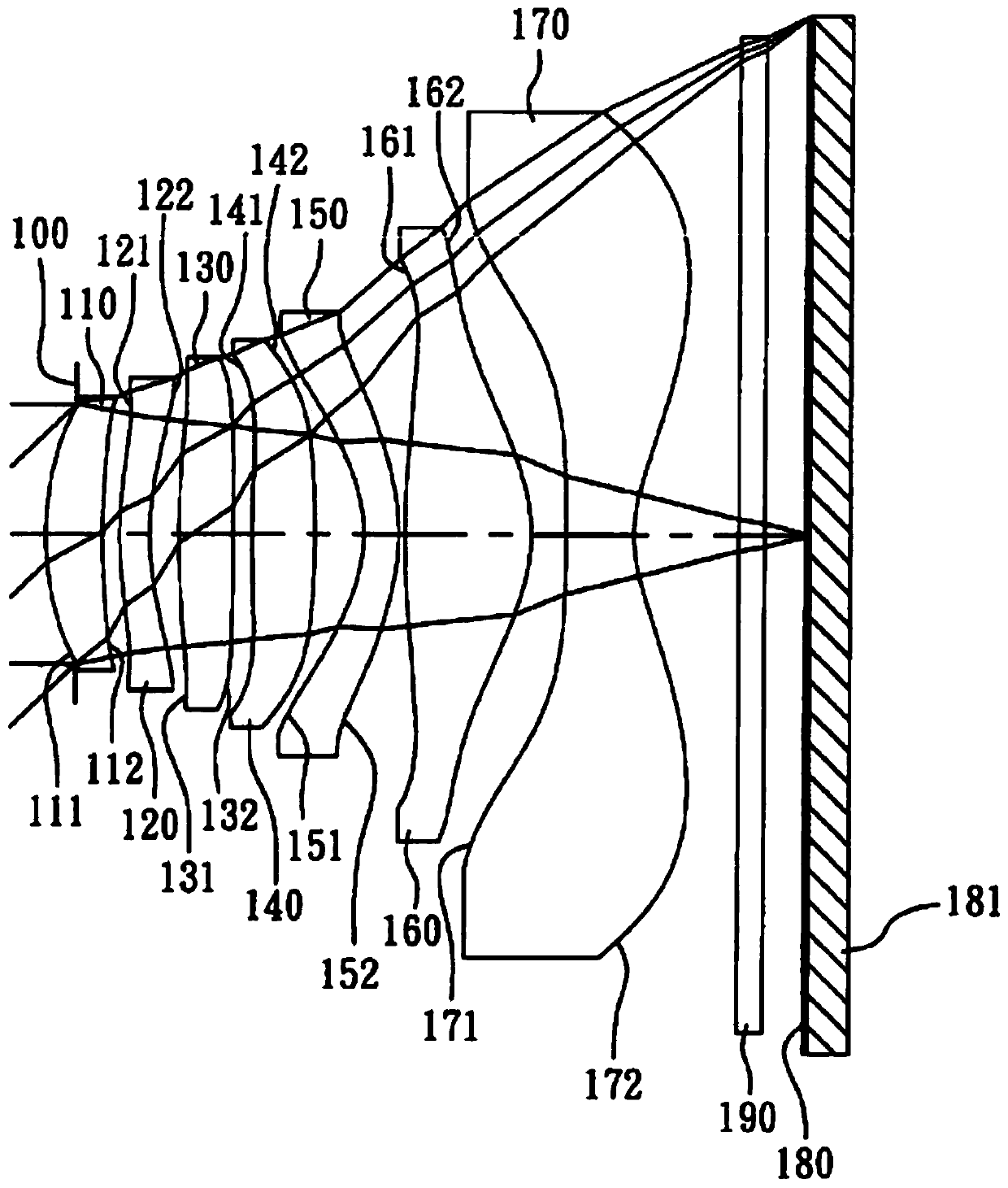
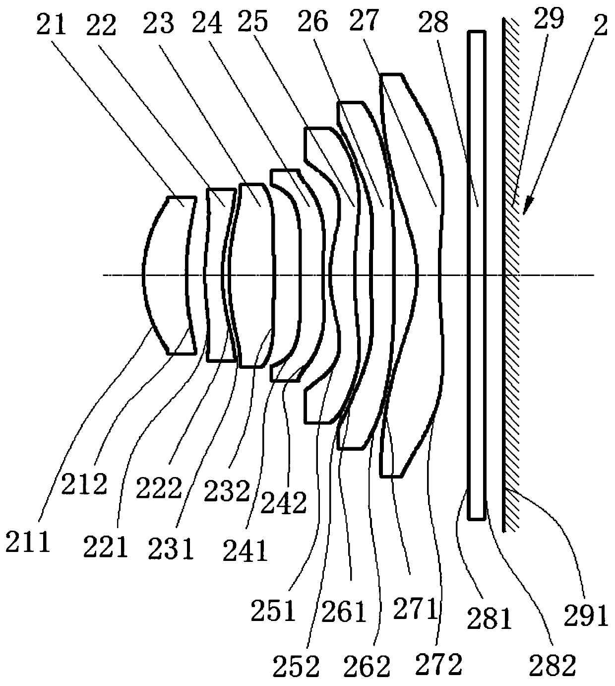
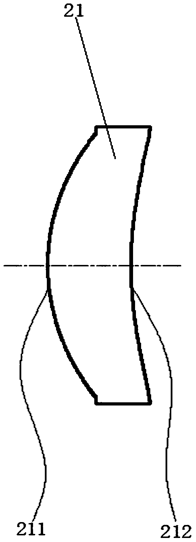
[0061] Please refer to Figure 2 to Figure 9 , the first embodiment provides an optical imaging system, the optical imaging system 2 is a seven-piece aspherical structure, including a first lens 21, a second lens 22, a third lens arranged in sequence from the object side to the image side 23. The fourth mirror 24, the fifth mirror 25, the sixth mirror 26, the seventh mirror 27, the infrared filter 28 and the image sensor 29, the aperture stop of which is located on the object side surface 211 of the first mirror.

[0062] The range of the combined focal length of the optical imaging system 2 is: 3.65mm<f<7.5mm, and the diagonal size of the image is larger than 6.4mm. In the first embodiment, the combined focal length of the optical imaging system 2 is preferably: f=3.827817451978569 mm.

[0063] The cross-sectional view of the first lens 21 is as image 3 As shown, it has a positive diopter, the first lens 21 has a first lens object side surface 211 and a first lens image si...

Embodiment 2

[0090] Please refer to Figure 15 to Figure 22 , the second embodiment provides an optical imaging system, the optical imaging system 2 is a seven-piece aspherical structure, including a first lens 21, a second lens 22, and a third lens arranged in sequence from the object side to the image side 23. The fourth lens 24 , the fifth lens 25 , the sixth lens 26 , the seventh lens 27 , the infrared filter 28 and the image sensor 29 , the aperture stop of which is located on the image-side surface 212 of the first lens.

[0091] An optical imaging system 2 provided in Embodiment 2, its cross-sectional view is as follows Figure 15 As shown, the range of the combined focal length of the optical imaging system 2 is: 3.65mm<f<7.5mm, and its image diagonal size is greater than 6.4mm. In the second embodiment, the combined focal length of the optical imaging system 2 is preferably: f = 4.2878353mm.

[0092] The cross-sectional view of the first lens 21 is as Figure 16 As shown, it ha...

Embodiment 3

[0118] Please refer to Figure 26 to Figure 32 , the third embodiment provides an optical imaging system, the optical imaging system 2 is a seven-piece aspherical structure, including a first lens 21, a second lens 22, a third lens arranged in sequence from the object side to the image side 23. The fourth lens 24, the fifth lens 25, the sixth lens 26, the seventh lens 27, the infrared filter 28 and the image sensor 29, wherein the second lens 22 and the third lens 23 are glued together and glued together by Canadian glue , and its aperture stop is located on the image-side surface 212 of the first lens.

[0119] A kind of optical imaging system 2 provided by the third embodiment, its cross-sectional view is as follows Figure 26 As shown, the range of the combined focal length of the optical imaging system 2 is: 3.65mm<f<7.5mm, and the diagonal size of the image is larger than 6.4mm. In the first embodiment, the combined focal length of the optical imaging system 2 is prefera...


PUM


Abstract

The invention discloses an optical imaging system. The optical imaging system is of a seven-piece aspheric surface structure. The system comprises a first lens, a second lens, a third lens, a fourth lens, a fifth lens, a sixth lens, a seventh lens, an infrared filter and an image sensor which are sequentially arranged from an object side to an image side; the first lens has positive diopter; the second lens has negative diopter; the third lens has positive diopter; the fourth lens has diopter, the fifth lens has diopter, the object side surface of the fifth lens is in an inflection shape; thecentral part protrudes towards the object plane; edge parts of the fifth lens are bent in the object surface direction and are in 3 shape; the sixth lens has diopter; and the seventh lens has diopter.The stray light problem can be well solved, the tolerance sensitivity of the camera module to surface shape errors, eccentricity, concentricity and inclination errors is greatly reduced, and the yield of the camera module is improved.

Description

technical field [0001] The invention relates to an optical imaging system, and in particular to a miniaturized optical imaging system applied to electronic products. Background technique [0002] At present, the smart phones newly launched on the market have been continuously upgraded on the rear camera. In just a few years, the mobile phone camera is going from 6M → 8M → 13M → 16M → 24M → 48M → 64M → 108M, and the rear pixels are almost showing a trend of upgrading every year. According to the supply chain channels of the camera industry, some famous mobile phone manufacturers have planned to include 216M pixels in the development agenda in the next two years. Various mobile phone manufacturers win the market by continuously upgrading the camera pixels and adding camera functions. [0003] In order to obtain the continuous upgrading of mobile phone camera pixels, a major change in the current mobile phone camera technology is the use of larger-sized CMOS used in digital c...

Claims


Application Information

Patent Timeline
Patent Type & Authority Applications(China)
IPC IPC(8): G02B13/00G02B13/18
CPCG02B13/0015G02B13/0045
Inventor 郎欢标
Owner MIKOLTA OPTICAL TECH CO
Features
  • R&D
  • Intellectual Property
  • Life Sciences
  • Materials
  • Tech Scout
  • Unparalleled Data Quality
  • Higher Quality Content
  • 60% Fewer Hallucinations
Learn More