Novel comprehensive demonstration teaching aid
A comprehensive and teaching aid technology, applied in the field of teaching aids, can solve the problems of high price, unintuitive understanding, and large space occupation, and achieve the effect of small overall volume, rich components, and space saving
- Summary
- Abstract
- Description
- Claims
- Application Information
AI Technical Summary
Problems solved by technology
Method used
Image
Examples
Embodiment 1
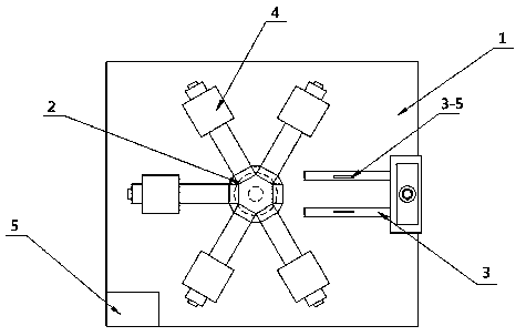
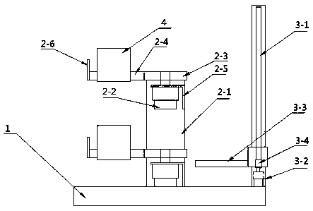
[0038] Embodiment 1, a kind of novel comprehensive demonstration teaching aid, structure such as figure 1 and figure 2As shown, it includes a fixed platform 1, a rotating mechanism 2, a lifting mechanism 3, a demonstration mechanism 4 and a control mechanism 5. The rotating mechanism 2, the lifting mechanism 3 and the control mechanism 4 are arranged on the fixed platform 1; the rotating mechanism 2 includes a support 2- 1 and a two-layer rotating mechanism distributed up and down along the support 2-1; the rotating mechanism includes a rotating motor 2-2, a rotating shaft 2-3 and a rotating member 2-4; the rotating motor 2-2 is fixed on the support by a motor bracket 2-5 On the seat 2-1; the rotating shaft 2-3 is connected with the output shaft of the rotating motor 2-2 through a coupling; the rotating part 2-4 is connected with the rotating shaft 2-3 through a top screw; there are several rotating parts 2-4, Symmetrical distribution along the axis of rotation 2-3;
[0039...
Embodiment 2
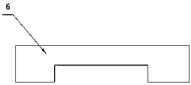
[0045] Embodiment 2 A new type of comprehensive demonstration teaching aid, refer to the structure figure 1 and 2 As shown, the difference from Example 1 is that the demonstration mechanism is a belt transmission mechanism, and the structure refers to Figure 4 shown. The belt transmission mechanism consists of a driving wheel 4-1-1, a driven wheel 4-1-2, a tensioning wheel 4-1-3, a synchronous belt 4-1-6 and a DC motor 4-1-7; the driving wheel One 4-1-1, driven wheel one 4-1-2 and tensioning wheel 4-1-3 are respectively fixed on the base 6 by fixture one 4-1-4; driving wheel one 4-1-1, slave Driving wheel one 4-1-2 and tensioning wheel 4-1-3 are connected with fixed piece one 4-1-4 through connecting shaft 4-1-5; the output shaft of DC motor 4-1-7 is through coupling It is connected with the connecting shaft of driving wheel one 4-1-1; driven wheel one 4-1-2 and driving wheel one 4-1-1 are connected through synchronous belt 4-1-6; tensioning wheel 4-1-3 Used to realize th...
Embodiment 3
[0046] Embodiment 3 A new type of comprehensive demonstration teaching aid, refer to the structure figure 1 and 2 As shown, different from Example 1,
[0047] The demonstration mechanism is a gear transmission mechanism, and the structure refers to Figure 5 shown. The gear transmission mechanism includes a gear one 4-2-1, a fixing part two 4-2-2, a motor and a base 6; a total of four gears one 4-2-1, which are fixed on the fixing part two 4-2-2 by a top screw On the four rotating shafts, four of the gears one 4-2-1 are scattered on the two fixed parts 4-2-2, and the adjacent gears one 4-2-1 mesh with each other; the motor is located on the two fixed parts 4-2-2. - On the rear side of 2-2, the output shaft of the motor is connected to the rightmost shaft through a coupling; driven by the motor, it drives the rightmost gear to rotate, and then drives the other three gears to drive to achieve demonstration Effect.
PUM
 Abstract
Description
Claims
Application Information
 - R&D
- Intellectual Property
- Life Sciences
- Materials
- Tech Scout
- Unparalleled Data Quality
- Higher Quality Content
- 60% Fewer Hallucinations
Browse by: Latest US Patents, China's latest patents, Technical Efficacy Thesaurus, Application Domain, Technology Topic, Popular Technical Reports.
© 2025 PatSnap. All rights reserved.Legal|Privacy policy|Modern Slavery Act Transparency Statement|Sitemap|About US| Contact US: help@patsnap.com


